
Page 45 - Applied Process Design For Chemical And Petrochemical Plants Volume III
P. 45
66131_Ludwig_CH10A 5/30/2001 4:08 PM Page 35
Heat Transfer 35
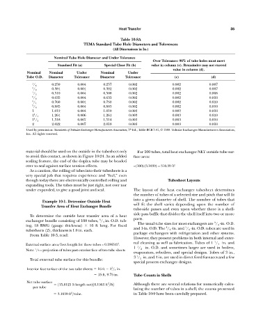
Table 10-8A
TEMA Standard Tube Hole Diameters and Tolerences
(All Dimensions in In.)
Nominal Tube Hole Diameter and Under Tolerance
Over Tolerance: 96% of tube holes must meet
Standard Fit (a) Special Close Fit (b) value in column (c). Remainder may not exceed
value in column (d).
Nominal Nominal Under Nominal Under
Tube O.D. Diameter Tolerance Diameter Tolerance (c) (d)
1 0.259 0.004 0.257 0.002 0.002 0.007
/ 4
3 0.384 0.004 0.382 0.002 0.002 0.007
/ 8
1 0.510 0.004 0.508 0.002 0.002 0.008
/ 2
5 0.635 0.004 0.633 0.002 0.002 0.010
/ 8
3 0.760 0.004 0.758 0.002 0.002 0.010
/ 4
7 0.885 0.004 0.883 0.002 0.002 0.010
/ 8
1 1.012 0.004 1.010 0.002 0.002 0.010
1 1.264 0.006 1.261 0.003 0.003 0.010
1 / 4
1 1.518 0.007 1.514 0.003 0.003 0.010
1 / 2
2 2.022 0.007 2.018 0.003 0.003 0.010
th
Used by permission: Standards of Tubular Exchanger Manufacturers Association, 7 Ed., Table RCB 7.41, © 1988. Tubular Exchanger Manufacturers Association,
Inc. All rights reserved.
material should be used on the outside in the tubesheet only For 100 tubes, total heat exchanger NET outside tube sur-
to avoid this contact, as shown in Figure 10-24. As an added face area:
sealing feature, the end of the duplex tube may be beaded
over to seal against surface tension effects. =(100)(3.1039) = 310.39 ft 2
As a caution, the rolling of tubes into their tubesheets is a
very special job that requires experience and “feel,” even
though today there are electronically controlled rolling and Tubesheet Layouts
expanding tools. The tubes must be just right, not over nor
under expanded, to give a good joint and seal. The layout of the heat exchanger tubesheet determines
the number of tubes of a selected size and pitch that will fit
into a given diameter of shell. The number of tubes that
Example 10-1. Determine Outside Heat
will fit the shell varies depending upon the number of
Transfer Area of Heat Exchanger Bundle
tube-side passes and even upon whether there is a shell-
side pass baffle that divides the shell itself into two or more
To determine the outside heat transfer area of a heat
3
exchanger bundle consisting of 100 tubes, / 4 in. O.D. tub- parts.
3
The usual tube sizes for most exchangers are / 4 -in. O.D.
ing, 18 BWG (gauge thickness) 16 ft long. For fixed
5
1
and 1-in. O.D. The / 8 -in. and / 2 -in. O.D. tubes are used in
tubesheets (2), thickness is 1.0 in. each.
package exchangers with refrigeration and other systems.
From Table 10-3, read:
However, they present problems in both internal and exter-
1
nal cleaning as well as fabrication. Tubes of 1 / 4 in. and
2
External surface area/foot length for these tubes = 0.1963 ft .
1
1 / 2 in. O.D. and sometimes larger are used in boilers,
1
Note: /8 = projection of tubes past exterior face of two tube sheets
evaporators, reboilers, and special designs. Tubes of 3 in.,
1
3 / 2 in. and 4 in. are used in direct fired furnaces and a few
Total external tube surface for this bundle:
special process exchanger designs.
1
Interior face-to-face of the two tube sheets 16 ft 2 > 4 in.
15 ft, 9.75 in. Tube Counts in Shells
Net tube surface 2
115.8125 ft length net210.1963 ft >ft2 Although there are several relations for numerically calcu-
per tube
lating the number of tubes in a shell, the counts presented
2
3.1039 ft >tube. in Table 10-9 have been carefully prepared.