Page 41 - Applied Process Design For Chemical And Petrochemical Plants Volume III
P. 41

66131_Ludwig_CH10A  5/30/2001 4:08 PM  Page 31


                                                                    Heat Transfer                                           31


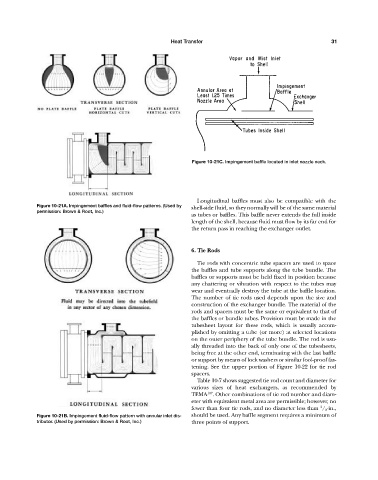
                                                                           Figure 10-21C. Impingement baffle located in inlet nozzle neck.


                                                                             Longitudinal baffles must also be compatible with the
                     Figure 10-21A. Impingement baffles and fluid-flow patterns. (Used by  shell-side fluid, so they normally will be of the same material
                     permission: Brown & Root, Inc.)
                                                                           as tubes or baffles. This baffle never extends the full inside
                                                                           length of the shell, because fluid must flow by its far end for
                                                                           the return pass in reaching the exchanger outlet.


                                                                           6. Tie Rods

                                                                             Tie rods with concentric tube spacers are used to space
                                                                           the baffles and tube supports along the tube bundle. The
                                                                           baffles or supports must be held fixed in position because
                                                                           any chattering or vibration with respect to the tubes may
                                                                           wear and eventually destroy the tube at the baffle location.
                                                                           The number of tie rods used depends upon the size and
                                                                           construction of the exchanger bundle. The material of the
                                                                           rods and spacers must be the same or equivalent to that of
                                                                           the baffles or bundle tubes. Provision must be made in the
                                                                           tubesheet layout for these rods, which is usually accom-
                                                                           plished by omitting a tube (or more) at selected locations
                                                                           on the outer periphery of the tube bundle. The rod is usu-
                                                                           ally threaded into the back of only one of the tubesheets,
                                                                           being free at the other end, terminating with the last baffle
                                                                           or support by means of lock washers or similar fool-proof fas-
                                                                           tening. See the upper portion of Figure 10-22 for tie rod
                                                                           spacers.
                                                                             Table 10-7 shows suggested tie rod count and diameter for
                                                                           various sizes of heat exchangers, as recommended by
                                                                                 107
                                                                           TEMA . Other combinations of tie rod number and diam-
                                                                           eter with equivalent metal area are permissible; however, no
                                                                                                                        3
                                                                           fewer than four tie rods, and no diameter less than  / 8 -in.,
                     Figure 10-21B. Impingement fluid-flow pattern with annular inlet dis-  should be used. Any baffle segment requires a minimum of
                     tributor. (Used by permission: Brown & Root, Inc.)    three points of support.
   36   37   38   39   40   41   42   43   44   45   46