
Page 38 - Applied Process Design For Chemical And Petrochemical Plants Volume III
P. 38
66131_Ludwig_CH10A 5/30/2001 4:08 PM Page 28
28 Applied Process Design for Chemical and Petrochemical Plants
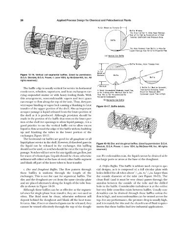
Figure 10-16. Vertical cut segmental baffles. (Used by permission:
B.G.A. Skrotzki, B.G.A. Power, © June 1954, by McGraw-Hill, Inc. All
rights reserved.)
The baffle edge is usually vertical for service in horizontal
condensers, reboilers, vaporizers, and heat exchangers car-
rying suspended matter or with heavy fouling fluids. With
this arrangement, noncondensable vapors and inert gases
can escape or flow along the top of the unit. Thus, they pre-
vent vapor binding or vapor lock causing a blanking to heat
Figure 10-17. Baffle details.
transfer of the upper portion of the shell. Also as important
as vapor passage is liquid released from the lower portion of
the shell as it is produced. Although provision should be
made in the portion of the baffle that rests on the lower por-
tion of the shell for openings to allow liquid passage, it is a
good practice to use the vertical baffle cut to allow excess
liquid to flow around the edge of the baffle without building
up and blanking the tubes in the lower portion of the
exchanger, Figure 10-17.
The horizontal cut baffles are good for all gas-phase or all
liquid-phase service in the shell. However, if dissolved gases in
Figure 10-18. Disc and doughnut baffles. (Used by permission: B.G.A.
the liquid can be released in the exchanger, this baffling Skrotzki, B.G.A. Power, © June 1954, by McGraw-Hill, Inc. All rights
should not be used, or notches should be cut at the top for gas reserved.)
passage. Notches will not serve for any significant gas flow, just
for traces of released gas. Liquids should be clean; otherwise nut. If condensables exist, the liquid cannot be drained with-
sediment will collect at the base of every other baffle segment out large ports or areas at the base of the doughnut.
and blank off part of the lower tubes to heat transfer.
d. Orifice Baffles. This baffle is seldom used except in spe-
c. Disc and Doughnut Baffles. The flow pattern through cial designs, as it is composed of a full circular plate with
1
1
these baffles is uniform through the length of the holes drilled for all tubes about / 16 -in. to / 8 -in. larger than
exchanger. This is not the case for segmental baffles. The the outside diameter of the tube (see Figure 10-19). The
disc and the doughnut are cut from the same circular plate clean fluid (and it must be very clean) passes through the
and are placed alternately along the length of the tube bun- annulus between the outside of the tube and the drilled
dle as shown in Figure 10-18. hole in the baffle. Considerable turbulence is at the orifice
Although these baffles can be as effective as the segmen- but very little cross-flow exists between baffles. Usually con-
tal ones for single-phase heat transfer, they are not used as densables can be drained through these baffles unless the
often. The fluid must be clean; otherwise sediment will flow is high, and noncondensables can be vented across the
deposit behind the doughnut and blank off the heat trans- top. For any performance, the pressure drop is usually high,
fer area. Also, if inert or dissolved gases can be released, they and it is mainly for this and the cleanliness of fluid require-
cannot be vented effectively through the top of the dough- ments that these baffles find few industrial applications.