
Page 37 - Applied Process Design For Chemical And Petrochemical Plants Volume III
P. 37
66131_Ludwig_CH10A 5/30/2001 4:08 PM Page 27
Heat Transfer 27
Table 10-6
Maximum Unsupported Straight Tube Spans
(All Dimensions in In.)
Tube Materials and Temperature Limits (°F)
Carbon Steel & High Alloy Steel (750)
Low Alloy Steel (850)
Nickel-Cooper (600)
Nickel (850) Aluminum & Aluminum Alloys, Copper & Copper Alloys, Titanium
Tube O.D. Nickel-Chromium-Iron(1000) Alloys at Code Maximum Allowable Temperature
1 26 22
/ 4
3 35 30
/ 8
1 44 38
/ 2
5 52 45
/ 8
3 60 52
/ 4
7 69 60
/ 8
1 74 64
1 88 76
1 / 4
1 100 87
1 / 2
2 125 110
Notes:
(1) Above the metal temperature limits shown, maximum spans shall be reduced in direct proportion to the fourth root of the ratio of elastic modulus
at temperature to elastic modulus at tabulated limit temperature.
(2) In the case of circumferentially finned tubes, the tube O.D. shall be the diameter at the root of the fins and the corresponding tabulated or
interpolated span shall be reduced in direct proportion to the fourth root of the ratio of the weight per unit length of the tube, if stripped of fins
to that of the actual finned tube.
(3) The maximum unsupported tube spans in Table 10-6 do not consider potential flow-induced vibration problems. Refer to Section 6 for vibration
criteria.
th
(Used by permission: Standards of the Tubular Exchanger Manufacturers Association, 7 Ed., Table RCB 4.52, © 1988. Tubular Exchanger Manufacturers
Association, Inc. All rights reserved.)
ported by one support, the support plate must be alternated
in orientation in the shell. The approximate maximum
unsupported tube length and maximum suggested tube
support spacing are given in Table 10-6.
Although detailed calculations might indicate that for
varying materials with different strengths the spacing could
be different, it is usually satisfactory to follow the guides in
Table 10-6 for any material commonly used in heat
exchangers. Practice allows reasonable deviation without
risking trouble in the unit.
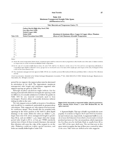
The tube support acts as a baffle at its point of installation Figure 10-15. Horizontal cut segmental baffles. (Used by permission:
B.G.A. Skrotzki, B.G.A. Power, © June 1954. McGraw-Hill, Inc. All
and should be so considered, particularly in pressure-drop
rights reserved.)
calculations. Tube supports are often ignored in heat trans-
fer coefficient design. They should also be provided with
openings in the lower portion at the shell to allow liquid b. Segmental Baffles. This type of baffle is probably the most
1
drainage to the outlet. Holes for tubes are drilled / 64 -in. popular. It is shown in Figures 10-15 and 10-16 for horizon-
larger than tube O.D. when unsupported length is greater tal and vertical cuts, respectively. A segmental baffle is a cir-
1
than 36 in. and are drilled / 32 -in. larger when the unsup- cle of near shell diameter from which a horizontal or vertical
ported tube length is 36 in. or less, per TEMA standards, portion has been cut. The cut-out portion, which represents
and are free of burrs. If there is much clearance, the natural the free-flow area for shell-side fluid, is usually from 20 to
flow vibration will cause the edge of the support to cut the near 50% of the open shell area. The net flow area in this
tube. Pulsating conditions require special attention, and space must recognize the loss of flow area covered by tubes
holes are usually drilled tight to tube O.D. in the area. Tube holes are drilled as for tube supports.