
Page 36 - Applied Process Design For Chemical And Petrochemical Plants Volume III
P. 36
66131_Ludwig_CH10A 5/30/2001 4:08 PM Page 26
26 Applied Process Design for Chemical and Petrochemical Plants
The baffle cut determines the fluid velocity between the baf- a. Tube Supports. Tube supports for horizontal exchangers
fle and the shell wall, and the baffle spacing determines the are usually segmental baffle plates cut off in a vertical plane
parallel and cross-flow velocities that affect heat transfer and to a maximum position of one tube past the centerline of
pressure drop. Often the shell side of an exchanger is sub- the exchanger and at a minimum position of the centerline.
ject to low-pressure drop limitations, and the baffle patterns The cut-out portion allows for fluid passage. Sometimes hor-
must be arranged to meet these specified conditions and at izontally cut plates are used when baffles are used in a shell,
the same time provide maximum effectiveness for heat trans- and extra tube supports may not be needed. It takes at least
fer. The plate material used for these supports and baffles two tube supports to properly support all the tubes in an
3
should not be too thin and is usually / 16 -in. minimum thick- exchanger when placed at maximum spacing. A tube will
1
ness to / 2 -in. for large units. TEMA has recommendations. sag and often vibrate to destruction if not properly sup-
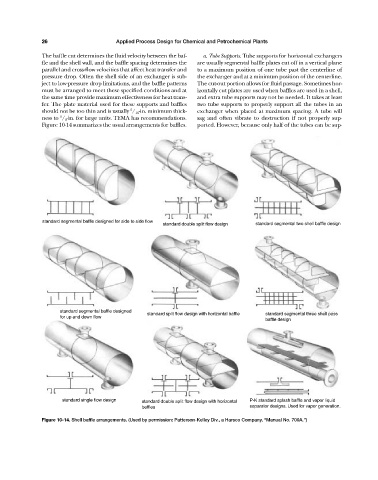
Figure 10-14 summarizes the usual arrangements for baffles. ported. However, because only half of the tubes can be sup-
standard segmental baffle designed for side to side flow
standard double split flow design standard segmental two shell baffle design
standard segmental baffle designed
standard split flow design with horizontal baffle standard segmental three shell pass
for up and down flow
baffle design
standard single flow design standard double split flow design with horizontal P-K standard splash baffle and vapor liquid
beffles separator designs. Used for vapor generation.
Figure 10-14. Shell baffle arrangements. (Used by permission: Patterson-Kelley Div., a Harsco Company, “Manual No. 700A.”)