
Page 40 - Applied Process Design For Chemical And Petrochemical Plants Volume III
P. 40
66131_Ludwig_CH10A 5/30/2001 4:08 PM Page 30
30 Applied Process Design for Chemical and Petrochemical Plants
exchanger. Some indications are that these stagnant par-
tially effective areas may be 10–20% of the total exchanger
55
surface in a 16-ft long bundle. It is apparent that this por-
tion of the design requires a close visualization of what will
17
occur as the fluid enters the unit. Braun suggests flow pat-
terns as shown in Figures 10-21A and 10-21B.
Some exchanger designs require that inlet nozzles be
placed close to the tubesheet to obtain the best use of the sur-
face in that immediate area. Fabrication problems limit this
dimension. Therefore, internal baffling must be used to force
the incoming fluid across the potentially stagnant areas.
g. Longitudinal Baffles. Longitudinal baffles are used on the
shell side of a unit to divide the shell-side flow into two or more
parts, giving higher velocities for better heat transfer, or to pro-
vide a divided area of the bundle for the subcooling of liquid
or the cooling of noncondensable vapors as they leave the
shell. The baffle must be effectively sealed at the shell to pre-
vent bypassing. Depending upon the shell diameter, the usual
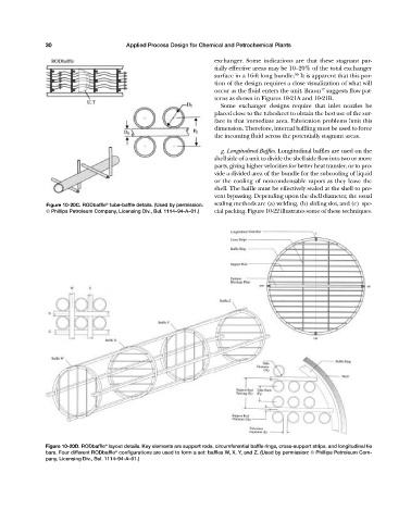
®
Figure 10-20C. RODbaffle tube-baffle details. (Used by permission: sealing methods are (a) welding, (b) sliding slot, and (c) spe-
© Phillips Petroleum Company, Licensing Div., Bul. 1114—94-A—01.) cial packing. Figure 10-22 illustrates some of these techniques.
Figure 10-20D. RODbaffle layout details. Key elements are support rods, circumferential baffle rings, cross-support strips, and longitudinal tie
®
bars. Four different RODbaffle configurations are used to form a set: baffles W, X, Y, and Z. (Used by permission: © Phillips Petroleum Com-
®
pany, Licensing Div., Bul. 1114—94-A—01.)