
Page 35 - Applied Process Design For Chemical And Petrochemical Plants Volume III
P. 35
66131_Ludwig_CH10A 5/30/2001 4:07 PM Page 25
Heat Transfer 25
those in the shell are adjusted by design to provide the nec-
essary arrangements for maintenance of proper heat trans-
fer fluid velocities and film conditions. Consider the two
classes of baffles described in the following sections.
A. Tube Side Baffles
These baffles are built into the head and return ends of
an exchanger to direct the fluid through the tubes at the
proper relative position in the bundle for good heat transfer
as well as for fixing velocity in the tubes, see Figures 10-1D
and 10-3.
Baffles in the head and return ends of exchangers are
either welded or cast in place. The arrangement may take
any of several reasonable designs, depending upon the
number of tube-side passes required in the performance of
the unit. The number of tubes per pass is usually arranged
about equal. However, depending upon the physical
changes in the fluid volume as it passes through the unit, the
number of tubes may be significantly different in some of
the passes. Practical construction limits the number of tube-
side passes to 8—10, although a larger number of passes may
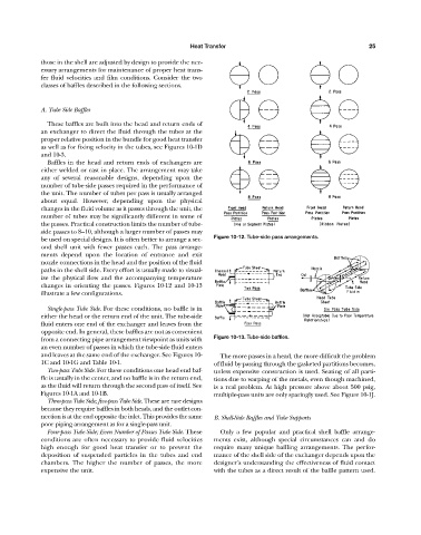
be used on special designs. It is often better to arrange a sec- Figure 10-12. Tube-side pass arrangements.
ond shell unit with fewer passes each. The pass arrange-
ments depend upon the location of entrance and exit
nozzle connections in the head and the position of the fluid
paths in the shell side. Every effort is usually made to visual-
ize the physical flow and the accompanying temperature
changes in orienting the passes. Figures 10-12 and 10-13
illustrate a few configurations.
Single-pass Tube Side. For these conditions, no baffle is in
either the head or the return end of the unit. The tube-side
fluid enters one end of the exchanger and leaves from the
opposite end. In general, these baffles are not as convenient
from a connecting pipe arrangement viewpoint as units with Figure 10-13. Tube-side baffles.
an even number of passes in which the tube-side fluid enters
and leaves at the same end of the exchanger. See Figures 10- The more passes in a head, the more difficult the problem
1C and 10-1G and Table 10-1. of fluid by-passing through the gasketed partitions becomes,
Two-pass Tube Side. For these conditions one head end baf- unless expensive construction is used. Seating of all parti-
fle is usually in the center, and no baffle is in the return end, tions due to warping of the metals, even though machined,
as the fluid will return through the second pass of itself. See is a real problem. At high pressure above about 500 psig,
Figures 10-1A and 10-1B. multiple-pass units are only sparingly used. See Figure 10-1J.
Three-pass Tube Side; five-pass Tube Side. These are rare designs
because they require baffles in both heads, and the outlet con-
nection is at the end opposite the inlet. This provides the same B. Shell-Side Baffles and Tube Supports
poor piping arrangement as for a single-pass unit.
Four-pass Tube Side; Even Number of Passes Tube Side. These Only a few popular and practical shell baffle arrange-
conditions are often necessary to provide fluid velocities ments exist, although special circumstances can and do
high enough for good heat transfer or to prevent the require many unique baffling arrangements. The perfor-
deposition of suspended particles in the tubes and end mance of the shell side of the exchanger depends upon the
chambers. The higher the number of passes, the more designer’s understanding the effectiveness of fluid contact
expensive the unit. with the tubes as a direct result of the baffle pattern used.