
Page 34 - Applied Process Design For Chemical And Petrochemical Plants Volume III
P. 34
66131_Ludwig_CH10A 5/30/2001 4:07 PM Page 24
24 Applied Process Design for Chemical and Petrochemical Plants
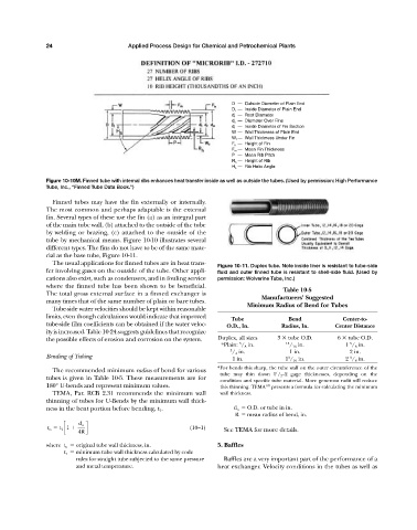
D — Outside Diameter of Plain End
D i — Inside Diameter of Plain End
d r — Root Diameter
d o — Diameter Over Fins
d i — Inside Diameter of Fin Section
W — Wall Thickness of Plain End
W f — Wall Thickness Under Fin
F h — Height of Fin
F m — Mean Fin Thickness
P — Mean Rib Pitch
R h — Height of Rib
H a — Rib Helix Angle
Figure 10-10M. Finned tube with internal ribs enhances heat transfer inside as well as outside the tubes. (Used by permission: High Performance
Tube, Inc., “Finned Tube Data Book.”)
Finned tubes may have the fin externally or internally.
The most common and perhaps adaptable is the external
fin. Several types of these use the fin (a) as an integral part
of the main tube wall, (b) attached to the outside of the tube
by welding or brazing, (c) attached to the outside of the
tube by mechanical means. Figure 10-10 illustrates several
different types. The fins do not have to be of the same mate-
rial as the base tube, Figure 10-11.
The usual applications for finned tubes are in heat trans-
Figure 10-11. Duplex tube. Note inside liner is resistant to tube-side
fer involving gases on the outside of the tube. Other appli- fluid and outer finned tube is resistant to shell-side fluid. (Used by
cations also exist, such as condensers, and in fouling service permission: Wolverine Tube, Inc.)
where the finned tube has been shown to be beneficial.
Table 10-5
The total gross external surface in a finned exchanger is
Manufacturers’ Suggested
many times that of the same number of plain or bare tubes.
Minimum Radius of Bend for Tubes
Tube-side water velocities should be kept within reasonable
limits, even though calculations would indicate that improved Tube Bend Center-to-
tube-side film coefficients can be obtained if the water veloc- O.D., In. Radius, In. Center Distance
ity is increased. Table 10-24 suggests guidelines that recognize
the possible effects of erosion and corrosion on the system. Duplex, all sizes 3 tube O.D. 6 tube O.D.
5
5
*Plain: / 8 in. 13 / 16 in. 1 / 8 in.
3 / 4 in. 1 in. 2 in.
Bending of Tubing 3 3
1 in. 1 / 16 in. 2 / 8 in.
*For bends this sharp, the tube wall on the outer circumference of the
The recommended minimum radius of bend for various
1
tube may thin down 1 / 2 —2 gage thicknesses, depending on the
tubes is given in Table 10-5. These measurements are for
condition and specific tube material. More generous radii will reduce
180° U-bends and represent minimum values. this thinning. TEMA 107 presents a formula for calculating the minimum
TEMA, Par. RCB 2.31 recommends the minimum wall wall thickness.
thinning of tubes for U-Bends by the minimum wall thick-
ness in the bent portion before bending, t 1 . d o O.D. or tube in in.
R mean radius of bend, in.
d o
t o t 1 c1 d (10—1)
4R See TEMA for more details.
where t o original tube wall thickness, in. 5. Baffles
t 1 minimum tube wall thickness calculated by code
rules for straight tube subjected to the same pressure Baffles are a very important part of the performance of a
and metal temperature. heat exchanger. Velocity conditions in the tubes as well as