
Page 39 - Applied Process Design For Chemical And Petrochemical Plants Volume III
P. 39
66131_Ludwig_CH10A 5/30/2001 4:08 PM Page 29
Heat Transfer 29
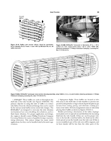
Figure 10-19. Baffles with annular orifices. (Used by permission: Figure 10-20B. RODbaffle Intercooler in fabrication, 67 in. 40 ft,
®
B.G.A. Skrotzki, B.G.A. Power, © June 1954, by McGraw-Hill, Inc. All 2,232– / 4 -in. O.D. copper-nickel tubes, 1.00 in. pitch. TEMA AHL.
3
rights reserved.) (Used by permission: © Phillips Petroleum Company, Licensing Div.,
Bul. 1114—94-A—01.)
®
Figure 10-20A. RODbaffle exchanger cross-section showing assembly, using TEMA E, F, H, J, K, and X shells. (Used by permission: © Phillips
Petroleum Company, Licensing Div., Bul. 1114—94-A—01.)
®
e. RODbaffles . These baffles are rods set throughout the f. Impingement Baffles. These baffles are located at inlet
shell side of the tube bundle (see Figures 10-20A—D). The flow areas to the shell side of tube bundles to prevent sus-
primary objective in using this style of baffle is to reduce pended solid particles or high-velocity liquid droplets in gas
tube failure from the vibrational damage that can be caused streams from cutting, pitting, and otherwise eroding por-
by the various metal baffles versus metal tube designs. The tions of the tubes. Several arrangements exist for effectively
®
RODbaffles are designed to overcome the tube vibration placing these baffles as shown in Figures 10-21A—C.
mechanisms of (a) vortex shedding, (b) turbulence, and (c) Besides preventing a destruction of the tubes, impinge-
fluid elastic vibration. For proper application and design, ment plates serve to spread out and distribute the incoming
the engineer should contact Phillips Petroleum Company fluid into the tube bundle. If they are used in proper rela-
Licensing Division for names of qualified design/manufac- tion to the bundle cross-flow baffles, the fluid can be effec-
turing fabricators. This unique design has many varied tively spread across the bundle near the inlet end. If this is
applications, but they can be handled only by licensed orga- not accomplished, part of the tube area will be stagnant, and
nizations. its heat transfer will be less than the other parts of the