
Page 215 -
P. 215
Gas and Liquid Injection Rates 177
flow exists when the in situ gas‒liquid ratio (GLR, dimensionless) is less
than unity. It also shows that a dispersed bubble flow occurs for superfi-
cial liquid velocities greater than 6 ft/sec and superficial gas velocities
as high as 12 ft/sec. The research work by Sunthankar and colleagues
(2001) on multiphase flow in an inclined well model confirmed Lage
and Time’s findings that a bubbly flow exists in the annular space when
the in situ GLR is less than unity. It can be shown that the in situ
GLR is greater than 1 only in a small portion of borehole sections (near
the surface) in the aerated liquid drilling practice (EMW between 4.0
and 6.9).
Although separated flow models are believed to be more accurate
than homogeneous flow models, the latter is still attractive and is widely
used due to its simplicity. In fact, it has been shown that the homoge-
neous flow models are accurate enough in UBD hydraulics calculations
(Guo et al., 1996; Guo et al., 2003; Sun et al., 2004).
Guo and Colleagues’ Homogeneous Flow Model
Guo and colleagues (1996) developed their first homogeneous flow
model using numerical integration. The model was validated with field
data from three wells at various depths. The model can simulate conven-
tional aeration, jet sub injection, and parasite tubing injection. In 2003,
Guo and colleagues presented a closed form hydraulics equation for pre-
dicting bottomhole pressure in UBD with foam. In 2004, Guo, Sun, and
colleagues published a closed form hydraulics equation for aerated mud
drilling in inclined wells. For simplicity, only the closed form models are
included in this section.
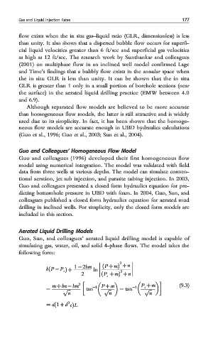
Aerated Liquid Drilling Models
Guo, Sun, and colleagues’ aerated liquid drilling model is capable of
simulating gas, water, oil, and solid 4-phase flows. The model takes the
following form:
2
bðP − P s Þ + 1 − 2bm ln ðP + mÞ + n
2
2 ðP s + mÞ + n
2 (9.3)
− m + bn − bm tan −1 P + m − tan −1 P s + m
p ffiffiffi p ffiffiffi p ffiffiffi
n n n
2
= að1 + d eÞL