
Page 218 -
P. 218
180 Part III Underbalanced Drilling Systems
The multiphase pressure drop at the bit can be expressed as (Guo et al.,
1996)
_
W 2 !
ΔP b = t 1 − 1 (9.14)
gA 2 γ γ
n dn up
where
2
ΔP b = pressure drop at bit (lbf/ft )
_ W t = total weight flow rate (lbf/s)
2
Α n = total bit nozzle area (ft )
γ = specific weight of mixture at downstream (lbf/ft )
3
dn
3
γ up = specific weight of mixture at upstream (lbf/ft )
This equation is valid for all multiphase flow, including aerated liquids
and foams.
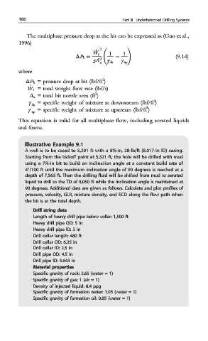
Illustrative Example 9.1
A well is to be cased to 5,291 ft with a 8⅝-in, 28-lb/ft (8.017-in ID) casing.
Starting from the kickoff point at 5,321 ft, the hole will be drilled with mud
using a 7⅞-in bit to build an inclination angle at a constant build rate of
4°/100 ft until the maximum inclination angle of 90 degrees is reached at a
depth of 7,563 ft. Then the drilling fluid will be shifted from mud to aerated
liquid to drill to the TD of 8,050 ft while the inclination angle is maintained at
90 degrees. Additional data are given as follows. Calculate and plot profiles of
pressure, velocity, GLR, mixture density, and ECD along the flow path when
the bit is at the total depth.
Drill string data
Length of heavy drill pipe below collar: 1,500 ft
Heavy drill pipe OD: 5 in
Heavy drill pipe ID: 3 in
Drill collar length: 480 ft
Drill collar OD: 6.25 in
Drill collar ID: 2.5 in
Drill pipe OD: 4.5 in
Drill pipe ID: 3.643 in
Material properties
Specific gravity of rock: 2.65 (water = 1)
Specific gravity of gas: 1 (air = 1)
Density of injected liquid: 8.4 ppg
Specific gravity of formation water: 1.05 (water = 1)
Specific gravity of formation oil: 0.85 (water = 1)