
Page 217 -
P. 217
Gas and Liquid Injection Rates 179
The positive and negative signs in Eq. (9.8) are the upward and down-
ward flows, respectively.
Determining the friction factor for multiphase flows presents a major
challenge in hydraulics calculations. Although a number of friction factor
correlations have been used by previous investigators (Caetano et al.,
1992; Nakagawa et al., 1999; Lage and Time, 2000; Lyons et al., 2001),
their accuracies are debatable.
For aerated liquid flow, Guo, Sun, and colleagues proposed the
following friction factor expression:
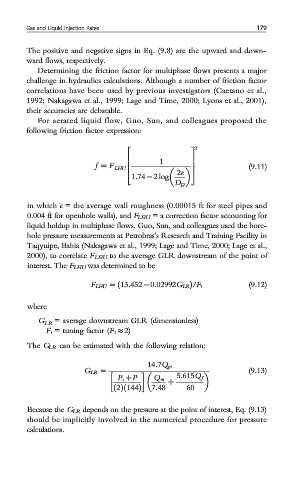
2
2 3
6 1 7
f = F LHU 6 7 (9.11)
2e
4 5
1:74 − 2 log
D H
in which e = the average wall roughness (0.00015 ft for steel pipes and
0.004 ft for openhole walls), and F LHU = a correction factor accounting for
liquid holdup in multiphase flows. Guo, Sun, and colleagues used the bore-
hole pressure measurements at Petrobras’s Research and Training Facility in
Taqyuipe, Bahia (Nakagawa et al., 1999; Lage and Time, 2000; Lage et al.,
2000), to correlate F LHU to the average GLR downstream of the point of
interest. The F LHU was determined to be
(9.12)
F LHU = ð13:452 − 0:02992G LR Þ/F t
where
G LR = average downstream GLR (dimensionless)
F t = tuning factor (F t ≈ 2)
The G LR can be estimated with the following relation:
14:7Q go
(9.13)
G LR =
P s + P Q m 5:615Q f
+
7:48 60
ð2Þð144Þ
Because the G LR depends on the pressure at the point of interest, Eq. (9.13)
should be implicitly involved in the numerical procedure for pressure
calculations.