
Page 170 - Applied Petroleum Geomechanics
P. 170
164 Applied Petroleum Geomechanics
5.1 In situ stresses in various faulting regimes
In situ stresses are the most important parameters for geomechanics
modeling and geoengineering design, particularly in the oil and gas
industry. For example, the minimum horizontal stress is very critical for
fracture gradient prediction, casing design and wellbore stability assessment
in drilling operations, and planning hydraulic fracturing in tight reservoirs.
Generally, in situ stresses include three mutually orthogonal principal
stresses in the subsurface, which can be defined as the vertical (overburden)
stress and the maximum and minimum horizontal stresses (s V , s H , and s h ).
In different geographic, geologic, and tectonic regions, in situ stress mag-
nitudes and orientations are very different. Three in situ stresses correspond
to three principal stresses, namely the greatest stress (s 1 ), the intermediate
stress (s 2 ), and the least stress (s 3 ). According to the relationship of these
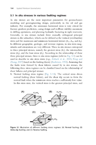
three principal stresses, three in situ stress regimes (refer to Fig. 5.1) can be
used to describe in situ stress states (e.g., Zoback et al., 2003; Peng and
Zhang, 2007) based on the faulting theory (Anderson, 1951). Assuming that
the faults were formed by shear failures caused by in situ stresses, the
following three stress regimes can be classified based on the relationship of
shear failures and principal stresses:
1. Normal faulting stress regime (Fig. 5.1A). The vertical stress drives
normal faulting (shear failure), and the shear slip occurs to form the
normal fault when the minimum stress reaches a sufficiently low value.
In this stress state, the vertical stress is the greatest principal stress, and
(A) σ =σ V (B) σ =σ V
2
1
α
σ =σ
α σ =σ h 1 H
3
σ =σ H σ =σ h
2
3
(C) σ =σ V
3
σ =σ
α 1 H
σ =σ h
2
Figure 5.1 Illustration of different faulting stress regimes: (A) Normal faulting; (B)
Strike-slip faulting; and (C) Reverse faulting.