
Page 233 - Applied Petroleum Geomechanics
P. 233
228 Applied Petroleum Geomechanics
6.5.2 From drilling-induced tensile fractures
Drilling-induced tensile fractures (DITFs) can be identified by borehole
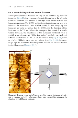
image log. Fig. 6.25 shows a section of electrical image log in the left and a
schematic wellbore cross section in the right with tensile fractures and
breakouts annotated. The DITFs and breakouts in the image log have low
resistivity for water-based mud (darker color). In the image log the
breakouts are wider and darker than the DITFs, and the directions of the
breakouts and DITFs are different in 90 degrees. For a vertical or nearly
vertical borehole, the orientation of the maximum horizontal stress is
parallel to the direction of DITFs. For inclined boreholes the angle (g)
between borehole axis and DITFs can be obtained using Eq. (6.68), when
en echelon DITFs in image logs are available (e.g., Fig. 6.14B). From the
image logs the maximum stress magnitudes can also be obtained for the
inclined boreholes (Thorsen, 2011).
Figure 6.25 Electrical image log (left) showing drilling-induced fractures and break-
outs in a vertical well with a schematic wellbore cross section (right) displaying the
directions of the DITFs and breakouts.