
Page 232 - Applied Petroleum Geomechanics
P. 232
In situ stress estimate 227
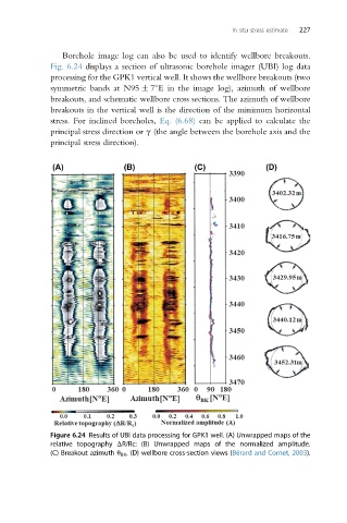
Borehole image log can also be used to identify wellbore breakouts.
Fig. 6.24 displays a section of ultrasonic borehole imager (UBI) log data
processing for the GPK1 vertical well. It shows the wellbore breakouts (two
symmetric bands at N95 7 E in the image log), azimuth of wellbore
breakouts, and schematic wellbore cross sections. The azimuth of wellbore
breakouts in the vertical well is the direction of the minimum horizontal
stress. For inclined boreholes, Eq. (6.68) can be applied to calculate the
principal stress direction or g (the angle between the borehole axis and the
principal stress direction).
Figure 6.24 Results of UBI data processing for GPK1 well. (A) Unwrapped maps of the
relative topography DR/Rc: (B) Unwrapped maps of the normalized amplitude.
(C) Breakout azimuth q BK . (D) wellbore cross-section views (Bérard and Cornet, 2003).