
Page 227 - Applied Petroleum Geomechanics
P. 227
222 Applied Petroleum Geomechanics
140
Horizontal DITF S UB
130 H
RF
120
T = 8 MPa T = 0 MPa Breakouts
110 Vertical DITF UCS = 100 MPa
(MPa) 100 Allowable UCS = 90 MPa
σ H , σ h area
σ H 90 SS
80 σ
NF v
70 h S LB
60 ν = 0.2
50
50 60 70 80 90 100 110 120 130 140
σ (MPa)
h
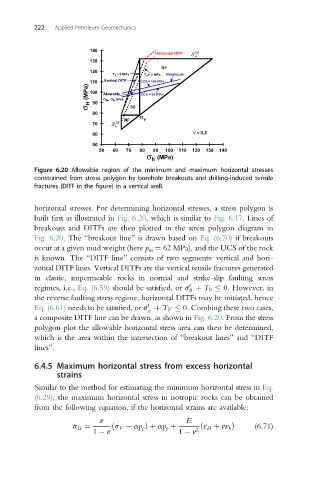
Figure 6.20 Allowable region of the minimum and maximum horizontal stresses
constrained from stress polygon by borehole breakouts and drilling-induced tensile
fractures (DITF in the figure) in a vertical well.
horizontal stresses. For determining horizontal stresses, a stress polygon is
built first as illustrated in Fig. 6.20, which is similar to Fig. 6.17. Lines of
breakouts and DITFs are then plotted in the stress polygon diagram in
Fig. 6.20. The “breakout line” is drawn based on Eq. (6.70) if breakouts
occur at a given mud weight (here p m ¼ 62 MPa), and the UCS of the rock
is known. The “DITF line” consists of two segments: vertical and hori-
zontal DITF lines. Vertical DITFs are the vertical tensile fractures generated
in elastic, impermeable rocks in normal and strike-slip faulting stress
0
regimes, i.e., Eq. (6.59) should be satisfied, or s þ T 0 0. However, in
q
the reverse faulting stress regime, horizontal DITFs may be initiated, hence
0
Eq. (6.61) needs to be satisfied, or s þ T V 0. Combing these two cases,
z
a composite DITF line can be drawn, as shown in Fig. 6.20. From the stress
polygon plot the allowable horizontal stress area can then be determined,
which is the area within the intersection of “breakout lines” and “DITF
lines”.
6.4.5 Maximum horizontal stress from excess horizontal
strains
Similar to the method for estimating the minimum horizontal stress in Eq.
(6.29), the maximum horizontal stress in isotropic rocks can be obtained
from the following equation, if the horizontal strains are available:
n E
s H ¼ ðs V ap p Þþ ap p þ ðε H þ nε h Þ (6.71)
1 n 1 n 2