
Page 224 - Applied Petroleum Geomechanics
P. 224
In situ stress estimate 219
polygon, i.e., s H S UB . Therefore, the ranges of horizontal stresses can be
H
obtained from Fig. 6.17, i.e., s h ¼ 82e87 MPa and s H ¼ 129e132 MPa.
6.4.2.2.2 For a horizontal well
For a horizontal well, drilling- or injection-induced horizontal fractures in
the reverse faulting stress regime are much easier to be generated because
the minimum effective tangential stress is very small. The minimum
effective tangential stress in a horizontal well drilled in the minimum
horizontal direction can be expressed in the following:
0
s ¼ 3s V s H p m ap p (6.65)
q
When the horizontal fractures (the fractures parallel to the axial direc-
tion of the horizontal well) are generated, the following relation is satisfied,
i.e., s þ T V 0. Notice that in this case s q is the stress to generate
0
0
q
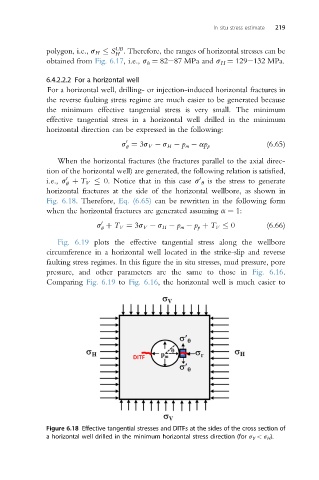
horizontal fractures at the side of the horizontal wellbore, as shown in
Fig. 6.18. Therefore, Eq. (6.65) can be rewritten in the following form
when the horizontal fractures are generated assuming a ¼ 1:
0
s þ T V ¼ 3s V s H p m p p þ T V 0 (6.66)
q
Fig. 6.19 plots the effective tangential stress along the wellbore
circumference in a horizontal well located in the strike-slip and reverse
faulting stress regimes. In this figure the in situ stresses, mud pressure, pore
pressure, and other parameters are the same to those in Fig. 6.16.
Comparing Fig. 6.19 to Fig. 6.16, the horizontal well is much easier to
Figure 6.18 Effective tangential stresses and DITFs at the sides of the cross section of
a horizontal well drilled in the minimum horizontal stress direction (for s V < s H ).