
Page 222 - Applied Petroleum Geomechanics
P. 222
In situ stress estimate 217
hydraulic fracture tests (e.g., DFIT, LOT) may not be representative of the
minimum horizontal stress. This closure pressure is the vertical stress instead.
Hence, an alternative method is needed for estimating the minimum
horizontal stress.
Horizontal fractures observed to open and dilate in the near-wellbore
environment can be used to constrain in situ stresses. Using Kirsch’s
equation, the minimum effective axial stress (s z ) at the wellbore wall in a
0
vertical well can be written as (refer to Eq. (10.30) in Chapter 10):
0
s ¼ s V 2nðs H s h Þ ap p (6.60)
z
Assuming that horizontal fractures are generated when s þ T V 0
0
z
0
(generating horizontal fracture) and s q þ T 0 > 0 (opposite to Eq. 6.59,
i.e., not generating vertical fracture), as shown in Fig. 6.16. Therefore,
Eqs. (6.60) and (6.58) can be rewritten as follows, assuming a ¼ 1:
0
s þ T V ¼ s V 2nðs H s h Þ p p þ T V 0 (6.61)
z
0
s þ T 0 ¼ 3s h s H p m p p þ T 0 > 0 (6.62)
q
where T V is the rock tensile strength for the vertical tensile stress (absolute
values for T V and T 0 are used in the equations), and it is the strength for
resistance to generate a horizontal tensile fracture and open it vertically.
If preexisting horizontal and low-angle fabrics or weaknesses (e.g., beddings
and interfaces) are presence, then T V is negligible. T 0 is the rock tensile
strength for the horizontal tensile stress.
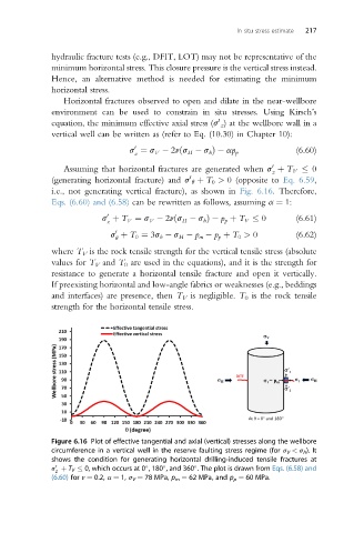
Figure 6.16 Plot of effective tangential and axial (vertical) stresses along the wellbore
circumference in a vertical well in the reserve faulting stress regime (for s V < s h ). It
shows the condition for generating horizontal drilling-induced tensile fractures at
s þ T V 0, which occurs at 0 , 180 , and 360 . The plot is drawn from Eqs. (6.58) and
0
z
(6.60) for n ¼ 0.2, a ¼ 1, s V ¼ 78 MPa, p m ¼ 62 MPa, and p p ¼ 60 MPa.