
Page 223 - Applied Petroleum Geomechanics
P. 223
218 Applied Petroleum Geomechanics
From Eqs. (6.61) to (6.62), the maximum horizontal stress can be
constrained in the following equations, and this condition represents the
case where only drilling- or injection-induced horizontal tensile fractures
are generated, i.e.,
s V þ 2ns h p p þ T V
Generating horizontal fractures : s H (6.63)
2n
(6.64)
Not generating vertical fractures : s H < 3s h p m p p þ T 0
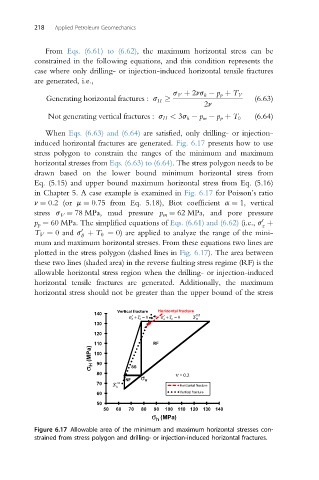
When Eqs. (6.63) and (6.64) are satisfied, only drilling- or injection-
induced horizontal fractures are generated. Fig. 6.17 presents how to use
stress polygon to constrain the ranges of the minimum and maximum
horizontal stresses from Eqs. (6.63) to (6.64). The stress polygon needs to be
drawn based on the lower bound minimum horizontal stress from
Eq. (5.15) and upper bound maximum horizontal stress from Eq. (5.16)
in Chapter 5. A case example is examined in Fig. 6.17 for Poisson’s ratio
n ¼ 0.2 (or m ¼ 0.75 from Eq. 5.18), Biot coefficient a ¼ 1, vertical
stress s V ¼ 78 MPa, mud pressure p m ¼ 62 MPa, and pore pressure
0
p p ¼ 60 MPa. The simplified equations of Eqs. (6.61) and (6.62) (i.e., s þ
z
0
T V ¼ 0 and s þ T 0 ¼ 0) are applied to analyze the range of the mini-
q
mum and maximum horizontal stresses. From these equations two lines are
plotted in the stress polygon (dashed lines in Fig. 6.17). The area between
these two lines (shaded area) in the reverse faulting stress regime (RF) is the
allowable horizontal stress region when the drilling- or injection-induced
horizontal tensile fractures are generated. Additionally, the maximum
horizontal stress should not be greater than the upper bound of the stress
Vertical fracture Horizontal fracture
140 UB
σ′ + T = 0 σ′ + T = 0 H S
130
120
110 RF
σ H (MPa) 100
90
80 SS ν = 0.2
NF σ v
70 h S LB Horizontal fracture
60 Vertical fracture
50
50 60 70 80 90 100 110 120 130 140
σ (MPa)
h
Figure 6.17 Allowable area of the minimum and maximum horizontal stresses con-
strained from stress polygon and drilling- or injection-induced horizontal fractures.