
Page 311 - Applied Photovoltaics
P. 311
where Ș mppt is the MPPT efficiency (typically 95%).
Therefore
Ș in = 0.0975 × 0.85 × 0.95 × 0.90
= 0.071
and, from Eqn. (G.3)
A = 5000/(4300 × 0.071 × 0.72)
= 22.8 m 2
or, in terms of the manufacturer’s ratings (at 25°C)
2
array rating = 1000 W/m × 0.10 × 22.8 m 2
= 2.28 kW p .
This compares to the 3.0 kW p rating required without the MPPT. A trade off
obviously exists between cost, system complexity, system efficiency and reliability.
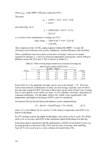
These calculations have been done on the basis of design 2 and can be simply
repeated for designs 1, 3 and 4 by using the appropriate nomograms, which will give
different values for POA and S. This is shown in Table G.2.
Table G.2. Plane-of-array design insolations as a function of storage (S).
2
plane-of array insolation (kWh/m /day)
tilt angle = latitude +
Design –20° –10° 0° 10° 20° S (days)
1 3.00 3.23 3.37 3.44 3.45 3.59
2 3.53 3.93 4.28 4.50 4.46 5.80
3 3.73 4.21 4.61 4.84 4.71 8.13
4 3.85 4.38 4.79 4.99 4.79 10.19
From Table G.2, the optimum tilt angle can be seen to be latitude + 10°. This then
leaves four potential combinations of array size and storage capacity, each of which
provides the required LOLP. Selection is then made on the basis of least cost. Costing
may be done purely on an initial cost basis, or else a lifetime cost basis, depending on
consumer preference. For the latter, battery life, which varies significantly with
temperature and depth-of-discharge (DOD), must be considered.
The battery life for flooded lead acid batteries can be estimated from
CL 89 59 . 29 T . 194 75 u DOD exp (G.7)
1
.
where CL is the battery life (in cycles), T is the battery temperature and DOD is the
depth-of-discharge.
In a PV-storage system, the depth-of-discharge varies from cycle to cycle. We define
each cycle as one day, and DOD as the maximum depth-of-discharge for that day.
It has been shown statistically that the distribution of DODs for all battery cycles can
be generalised as a function of the LOLP and the days of storage, thus enabling
Eqn. (G.7) to be used to give a close estimate of actual battery life.
298