
Page 52 - Applied Photovoltaics
P. 52
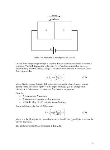
holes
                                                          electrons


                                                      p               n


                                                          V


                                           Figure 2.10. Application of a voltage to a p-n junction.


                          Once Ê is no longer large enough to stop the flow of electrons and holes, a current is
                          produced. The built in potential reduces to V bi  – V and the current flow increases
                          exponentially with the applied voltage. This phenomenon results in the Ideal Diode
                          Law, expressed as
                                                           ª   § qV  ·  º
                                                      I    I 0  « exp ¨  ¸   1 »        (2.2)
                                                           ¬   © kT  ¹  ¼
                          where I is the current, I 0  is the dark saturation current (the diode leakage current
                          density in the absence of light), V is the applied voltage, q is the charge on an
                          electron, k is Boltzmann’s constant and T is absolute temperature.
                          Note that
                              x  I 0 increases as T increases
                              x  I 0 decreases as material quality increases
                              x  at 300 K, kT/q = 25.85 mV, the thermal voltage.
                          For actual diodes, the Eqn. (2.2) becomes

                                                          ª   § qV  ·  º
                                                     I    I  exp ¨  ¸   1               (2.3)
                                                         0 «           »
                                                          ¬   © nkT  ¹  ¼
                          where n is the ideality factor, a number between 1 and 2 that typically increases as the
                          current decreases.
                          The diode law is illustrated for silicon in Fig. 2.11.


                                                                                                 39