
Page 75 - Applied Photovoltaics
P. 75
4.3 RECOMBINATION LOSSES
The efficiency of a solar cell is also reduced by the recombination of electron-hole
pairs before they can be usefully collected (Green, 1986). A number of recombination
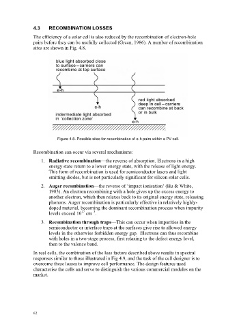
sites are shown in Fig. 4.8.
Figure 4.8. Possible sites for recombination of e-h pairs within a PV cell.
Recombination can occur via several mechanisms:
1. Radiative recombination—the reverse of absorption. Electrons in a high
energy state return to a lower energy state, with the release of light energy.
This form of recombination is used for semiconductor lasers and light
emitting diodes, but is not particularly significant for silicon solar cells.
2. Auger recombination—the reverse of ‘impact ionisation’ (Hu & White,
1983). An electron recombining with a hole gives up the excess energy to
another electron, which then relaxes back to its original energy state, releasing
phonons. Auger recombination is particularly effective in relatively highly-
doped material, becoming the dominant recombination process when impurity
17
–3
levels exceed 10 cm .
3. Recombination through traps—This can occur when impurities in the
semiconductor or interface traps at the surfaces give rise to allowed energy
levels in the otherwise forbidden energy gap. Electrons can thus recombine
with holes in a two-stage process, first relaxing to the defect energy level,
then to the valence band.
In real cells, the combination of the loss factors described above results in spectral
responses similar to those illustrated in Fig 4.9, and the task of the cell designer is to
overcome these losses to improve cell performance. The design features used
characterise the cells and serve to distinguish the various commercial modules on the
market.
62