
Page 79 - Applied Photovoltaics
P. 79
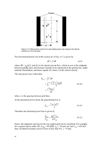
fingers
dy
b
y
s/2
Figure 4.13. Dimensions needed for calculating power loss owing to the lateral
resistance of the top layer.
The incremental power loss in the section dy of Fig. 4.13 is given by
dP I 2 dR (4.9)
where dR = ȡ dy/b, and I(y) is the lateral current flow, which is zero at the midpoint
between grating lines and increases linearly to its maximum at the grating line, under
uniform illumination, and hence equals Jby where J is the current density.
The total power loss is therefore
P loss ³ I 2 dR
s 2 / J 2 b 2 y 2 ȡ dy
³ 0 b (4.10)
J 2 ȡ b s 3
24
where s is the spacing between grid lines.
At the maximum power point, the generated power is
V mp J mp bs
P gen (4.11)
2
Therefore the fractional power loss is given by
P loss ȡ s 2 J mp
(4.12)
P gen 12 V mp
Hence, the minimum spacing for the top contact grid can be calculated. For example,
2
for a typical silicon solar cell, if ȡ = 40 ȍ/, J mp = 30 mA/cm and V mp = 450 mV,
then, for lateral resistance power losses of less than 4%, s < 4 mm.
66