
Page 188 - APPLIED PROCESS DESIGN FOR CHEMICAL AND PETROCHEMICAL PLANTS, Volume 1, 3rd Edition
P. 188
0 SECURE LUBRICATION
Liquid fm thecasing flaws between
the rear casing and the magnet lining
whii prevents clogging. The fluid is
then forced to fkw to the rear bushing
then through the shaft to the front
bushing. This flow guarantees perfect
lubricaticm for the bushing.
0 LONG LIFE THRUST RING
The thrust ring is connected to the
magnet not to the impeller, which
reduces its rotating vebcity. The
lower velocity increases the life
of the thrust ring.
@ NO ADHESIVE
All of the bushings as well as the liner
ring and thrust ring are not attached by
adhesives. Thus the parts are easily
replaced and the parts are free from
any weakness of the adhesive.
standard materials: other materials BVE ation.
No. PattName Material
1 Liner Ring Carbon-filled PTFE
2 Impeller PVDF (KYNAR)"
3 I Casina I PVDF (KYNAR) I
4 I whipl late I PVDF (KYNAR) I
5 FrontBGhing Carbon-filled PTFE
6 Thrust Ring CERAMIC
7 Rearcasing Carbon-filled PVDF
8 OuterMagnet
9 InnerMagnet
10 Shaft CERAMIC
11 RearBushing Carbon-filled PTFE
12 -0, Ring VITON
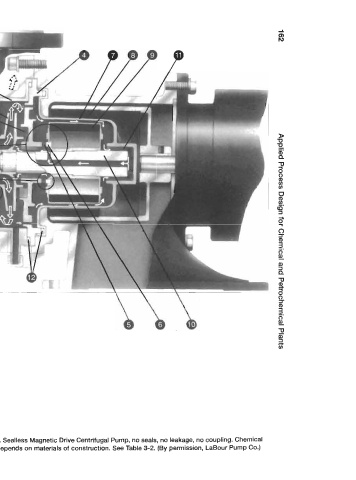
Figure 3-1A. Sealless Magnetic Drive Centrifugal Pump, no seals, no leakage, no coupling. Chemical