
Page 190 - APPLIED PROCESS DESIGN FOR CHEMICAL AND PETROCHEMICAL PLANTS, Volume 1, 3rd Edition
P. 190
Fluid at approximately 60% of discharge
pressure is circulated through the bear-
ings and over the rotor for cooling and
lubrication and returns through the hd-
low shaft to suction pressure.
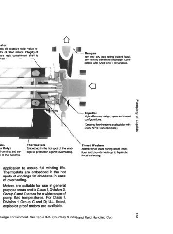
150 and 300 pslg rating (raised face).
Self venting centertine dkicharge. Com-
Terminal Plate patible with ANSI 873.1 dimensions.
oring sealing for positive secondary
fluid containment.
2
3
z.
3
(P
rotor sleeve since the contact tip is High efRdency design, open and closed 2
supplied in the same metallurgy but configurations. r
one-half the thickness of those compo- (optional now inducers availde for min- t.
nents.
imum NPSH requirements.) P
Shaft Sleeves v)
Available in a va
ments to suit the
tions. Replaced
Hollow Shaft (Basic, Thermostats Thrust Washers
clearances. Available in a variety of materials to suit HB and HX Models Only) Embedded in the hot spot of the wind- Absorb thrust loads during upset condi-
the specific fluid application. Oversized Assures complete self-venting and pre ings for protection against overheating. tions and provide back-up to hydraulic
for minimum loading. vents vapor collection at the bearings. thrust balancing.
Motors
In the Sundyne Canned Motor design, stator liner to cool the motor, and lubri- application to assure full winding life.
the entire outside of the motor is en- cate the bearings. Thermostats are embedded in the hot
dosed in a secondary leakage contain- Motor windings and insulation systems spots of windings for shutdown in case
ment shell or can. Primary leakage pro- are specially designed, developed and of overheating.
tection is provided by corrosion resistant applied as an integral part of the pump Motors are suitable for use in general
liners which are seal welded and 100% so that design life is at least as great as purpose areas and in Class I, Division 2,
leak checked to assure that pumped for conventional air cooled motors. Group C and D areas for a wide range of
fluid does not contact the stator windings Winding temperature k primarily Influ- pump fluid temperatures. For Class I,
or rotor core. There is no shaft protrusion enced by pumped fluid temperature and Division 1 Group C and D; U.L. listed,
to seal and thus no seals to leak. secondarily by use of cooling jacket. explosion proof motors are available.
Pumped fluid is circulated inside the Fluid temperature is considered in pump
Figure 3-1 B. Sealless canned centrifugal pump, primary and secondary le makage containment. See Table 3-2. (Courtesy Sundstrand Fluid Handling CO.) 8