
Page 213 - APPLIED PROCESS DESIGN FOR CHEMICAL AND PETROCHEMICAL PLANTS, Volume 1, 3rd Edition
P. 213
Pumping of Liquids 185
Figure 3-40D. Pressure head, positive suction. (Adapted by permis-
sion, Centrifugal Pumps Fundamentals, Ingersoll-Rand Co., Wash-
ington, N.J. 07882.)
Figure 3-4M. Static head, overall = H + e.. (Adapted by permission,
Centrifugal Pumps Fundamentals, Ingersoll-Rand Co., Washington,
N.J. Q7882.)
Figure 3-40B. Static head, overall = H - S. (Adapted by permission,
Centrifugal Pumps Funa'amentals, Bngersloll-Rand Co., Washington,
.J. 07882.)
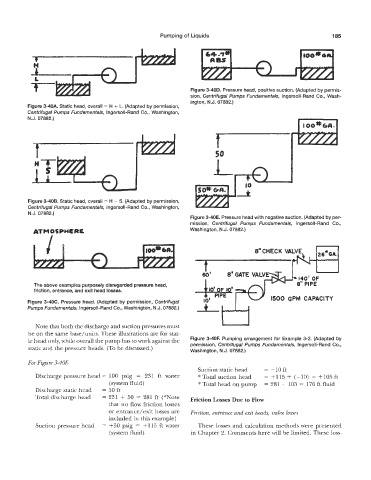
Figure 3-40E. Pressure head with negative suction. (Adapted by per-
mission, Centrifugal Pumps Fundamentals, Ingersoll-Rand Co.,
Washington, N.J. 07882.)
The above examples purposely disregarded pressure head,
friction, entrance, and exit head losses.
Figure 3-4OC. Pressure head. (Adapted by permission, Centrifugal
Sumps Fu~damenfa/s, Bngersoll-Rand Co., Washington, N.J. 07882.)
Kote that both the discharge and suction pressures must
be the same base/units. These illustrations are for stat-
ic head only, while ~erilll the pump has to work against the Figure 3-40!? Pumping arrangement for Example 3-2. (Adapted by
permission, Centrifugal Pumps Fundamentals, Ingersoll-Rand Co.,
static and the pressure heads. (To be discussed.) Washington, N.J. 07882.)
For Figure 3-4QE
Suction static head = -1Oft
Discharge pressure head = 100 psig = 231 ft water * Total suction head = +I15 + (-10) = +I05 ft
(system fluid) * Total head on pump = 281 - 105 = 176 ft fluid
Discharge static head = 50 ft
Total discharge head = 231 + 50 = 281 ft (*Note
that no flow friction losses
or entrarice/exit losses are Friction, entrance and exit heads, valve losses
included in this example)
Suction pressure head = +5Q psig = +115 ft water These losses and calculation methods were presented
(system fluid) in Chapter 2. Comments here will be limited. These loss-