
Page 212 - APPLIED PROCESS DESIGN FOR CHEMICAL AND PETROCHEMICAL PLANTS, Volume 1, 3rd Edition
P. 212
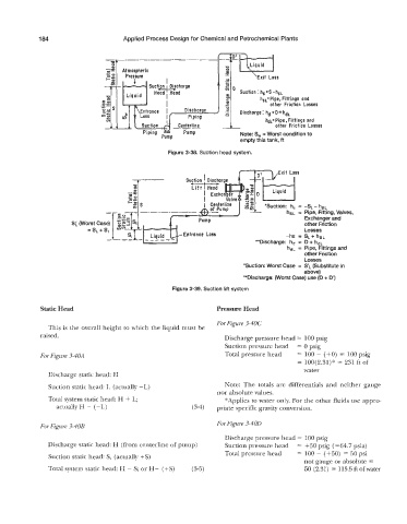
184                      Applied Process Design for Chemical and Petrochemical Plants

                                 -                           _-------
                                   ua
                                   0
                                       -
                                      Atmospheric                    -0 0
                                                                      P
                                       Pressure
                                                                      V  .-
                                                    I
                                                 4-
                                 4-       c   Suction  Discharge   IL   c
                                                                      a
                                                                      GO
                                       Liquid   Head  Head            a2   Suction: hs=S-hsL
                                                    I
                                 W                                    Y         h,,=Pipe,   Fittings and
                                                    I                 c            other  Friction Losses
                                                                      0
                                                                      u
                                                                      YI
                                                                      ;3   Discharge: hd 'D*hdL
                                                                                  hdL:Pipe,Fittings  and
                                                                                     other  Friction Losses
                                                                          fTRs

                                                                                    Liquid
                                                                                  *Suction:  h,  = -SL - hFL.
                                                                                        hSL =  Pipe, Fitting, Valves,
                                                                                              ExchanQer and
                       Si                                                                     other Friction
                                                                                              Losses
                                                         Entrance  Loss                 -hs  = SL+ hSL
                                                                               **Discharge:   hd  =  D + hdL
                                                                                         hdL = Pipe, Fittings and
                                                                                              other Friction
                                                                                              Losses
                                                                           *Suction: Worst Case  =  SIL (Substitute in
                                                                                              above)
                                                                           **Discharge: (Worst Case) use (D + D3
                                                      Figure 3-39. Suction lift system


              Static Head                                          Pressure Head

                                                                   For Figure 3-40C
                This is the overall height to which the liquid must be
              raised.                                                 Discharge pressure head = 100 psig
                                                                      Suction pressure head   = 0 psig
             For Figure 3-40A                                         Total pressure head   = 100 - (+O)  = 100 psig
                                                                                            = 100(2.31)* = 231 ft of
                                                                                              water
                Discharge static head: H
                Suction static head: L (actually -L)                  Note:  The  totals  are  differentials  and  neither  gauge
                                                                   nor absolute values.
                Total system static head: H + L;                      "Applies to water only. For the other fluids use appro-
                   actually H - (-L)                        (3-4)   priate specific gravity conversion.

                                                                   For Figure 3-400
              For Figure 3-4OB
                                                                      Discharge pressure head = 100 psig
                Discharge static head: H (from centerline of pump)    Suction pressure head   = t50 psig (=64.'7 psia)
                                                                      Total pressure head   = 100 - (+50) = 50 psi
                Suction static head: S, (actually +S)
                                                                                              not gauge or absolute =
                Total system static head: H  - S; or H-  (+S)   (3-5)                         50 (2.31) = 115.5 ft ofwater