
Page 215 - APPLIED PROCESS DESIGN FOR CHEMICAL AND PETROCHEMICAL PLANTS, Volume 1, 3rd Edition
P. 215
Pumping of Liquids 187
units and the discharge head must be calculated in Discharge Head, hd
absolute units.
5. Suction lift is a negative suction head, S, used to des- The discharge head of a pump is the head measured at
ignate a negative static condition on the suction of the discharge nozzle (gauge or absolute), and is com-
the pump (below atmospheric). The sign for suction posed of the same basic factors previously summarized; 1.
head is positive (+) , while its corresponding termi- static head 2. friction losses through pipe, fittings, con-
nology of suction lift is negative (-), since the term tractions, expansions, entrances and exits 3. terminal sys-
“lift” denotes a negative condition. Note that the only tem pressure.
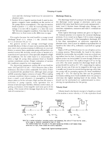
difference in these terms is the difference in signs. Some typical discharge systems are given in Figure 3-
42. General practice is to express the terminal discharge
This applies because the total head for a pump is total pressure, P, at a vessel as in Figure 3-42 in terms of gauge
discharge head a(+), minus (-) the [suction head, pressure, and hence P = 0 for atmospheric discharge. If P
a(+)], or [suction lifit, a(-)]. is less than atmospheric or otherwise expressed in
For general service the average centrifugal pump absolute units, then it must be added a3 equivalent feet of
should lift about 15 feet of water on its suction side. How- liquid to the value of hd ordinarily expressed as a gauge
ever, since each process situation is different, it is not suf- reading.
ficient to assume that a particular pump will perform the Figures 3-38 and 3-39 illustrate the use of siphon action
needed suction lift. ALctually, certain styles or models of a in pump systems. Theoretically, the head in the siphon
manufacturer‘s pumps are often specially adapted to high should be recoverable, but actually it may no~, at least not
lift conditions. On the other hand it is unnecessary to equivalent foot for foot. Usually not more than 20 feet of
select a high lift pump when pressure head or flooded siphon action can be included [4] even though 34 feet are
suction conditions prevail. Proper evaluation of suction theoretical at sea level. The siphon length is D’ in the fig-
lift conditions cannot be over emphasized. ures [32]. For some systems the discharge head on the
The theoretical maximum suction lift at sea level for pump should be used as (I3 + D’) , neglecting the siphon
water (14.7 psi) (2.31 ft/psi) = 34 ft. However, due to flow action. In any case, if air can be trapped in the loop, (and
resistance, this value 11s never attainable. For safety, 15 feet it usually can) it must be vented during start-up, otherwise
is con sidered the pr,actical limit, although some pumps the pump will be pumping against the head established
will lift somewhat higher cotumns of water. When sealing using (D + D’). On start-up the flow can be gradually
a vacuum condition above a pump, or the pump pumps increased, making more head available from the pump to
from a vessel, a seal allowance to atmosphere is almost overcome the higher starting head of the system. This
always taken as 34 feet of water. High suction lift causes a should not be overlooked nor underestimated in deter-
reduction in pum capacity, noisy operation due to mining the specifications for the pump.
release of air and vapor bubbles, vhation and erosion, or
pitting (cavitation) of the impeller and some parts of the Velocity Head
casing. (The extent of the damage depends on the mate-
rials of construction.) Velocity head is the kinetic energy of a liquid as a result
of its motion at some velocity, v. It is the equivalent head
Atmospheric
Pressure
Entrance Loss (EL)
Pump Pump
hd = D + hdL
(c9
Note: For a system evaluation, including suction and discharge, the units of P must be the same
either gage or absolute ,expressed as feet of fluid.
The friction losses from the pump to the vessel include any entrance or exit Iosses.Un!ess
velocities are high, these losses are usually negligible.
Figure 3-42. Typical discharge systems.