
Page 135 - Applied Process Design For Chemical And Petrochemical Plants Volume II
P. 135
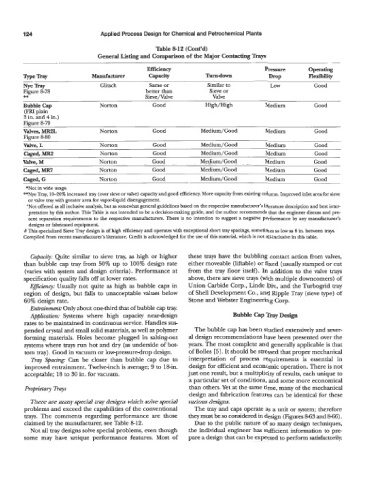
124                      Applied Process Design for Chemical and Petrochemical Plants

                                                     Table 8-12 (Cont’d)
                                 General Listing and Comparison of the Major Contacting Trays
                                                             ._                                              .-
                                                  Efficiency                            Pressure       OPrnting
         vPeTr?ry              Manufacturer       Capacity           Turn-down            WOP          Flexibility
         Fe Tray                  Glitsch         Same or            Similar to           Low            Good
         Figure 8-78                             better than          Sieve or
         **                                      Sieve/Valve           Valve
         Bubble Cap               Norton           Good              High/High           Medium          Good
         (FRI plain
         3 in. and 4 in.)
         Fimre 8-79
         valves, MR2L             Norton           Good            Medium/Good           Medium          Good
         Figure 8-80
         Valve, L                 Norton           Good            Medium/Good           Medium          Good
         Caged, MR2               Norton            Good           Medium/Good           Medium          Good
         Valve, M                 Norton            Good           Medium/Good           Medium          Good
         Caged, MR?               Norton            Good           Medium/Good           Medium          Good
         Caged, G                 Norton            Good           Medium/Good           Medium          Good
          *Not in wide usage.
         **Nye Tray, 10-20%  increased tray (over sieve or valve) capacity and good efficiency. More capacity from existing column. Improved inlet area for sieve
           or valve tray with greater area for vapor-liquid disengagement.
          +Not offered as all inclusive analysis, but as somewhat general guidelines based on the respective manufacturer’s literature description and best inter-
           pretation by this author. This Table is not intended to be a decision-making guide, and the author recommends that the engineer discuss and pre-
           sent separation requirements  to the respective manufacturers. There is no intention  to suggest a negative performance  by  any manufacturer’s
           designs or fabricated equipment.
         # This specialized Sieve Tray design is of high efficiency and operates with exceptional short tray spacings, sometimes as low as 6 in. between trays.
         Compiled from recent manufacturer’s literature. Credit is acknowledged for the use of this material, which is not all-inclusive in this table.


           Capacity: Quite  similar to sieve tray, as high or higher   these trays have the bubbling contact action from valves,
         than bubble cap tray from 50% up to  100% design rate   either moveable (liftable) or fixed (usually stamped or cut
         (varies with  system and design criteria). Performance at   from the tray floor itself). In addition to the valve  trays
         specification quality falls off at lower rates.       above, there are sieve trays (with multiple downcomers) of
           EfJiciency: Usually not  quite as high as bubble caps in   Union Carbide Corp., Linde Div., and the Turbogrid tray
         region of  design, but falls to unacceptable values below   of Shell Development Co., and Ripple Tray (sieve type) of
         60% design rate.                                      Stone and Webster Engineering Corp.
           Entrainment: Only about one-third that of bubble cap tray.
           Application: Systems  where  high  capacity  neardesign            Bubble Cap Tray Design
         rates to be maintained in continuous service. Handles sus
         pended crystal and small solid materials, as well as polymer   The bubble cap has been studied extensively and sever-
         forming materials. Holes become plugged  in  salting-out   al design recommendations have been presented over the
         systems where trays run hot and dry (as underside of bot-   years. The most complete and generally applicable is that
         tom tray). Good in vacuum or low-pressure-drop design.   of Bolles [5]. It should be stressed that proper mechanical
           Tray  Spacing: Can  be  closer  than  bubble  cap  due  to   interpretation  of  process  requirements  is  essential  in
         improved entrainment. Twelve-inch is average; 9 to 18-in.   design for efficient and economic operation. There is not
         acceptable; 18 to 30 in. for vacuum.                  just one result, but a multiplicity of results, each unique to
                                                               a particular set of conditions, and some more economical
         Pqtmetary Trays                                        than others. Yet at the same time, many of the mechanical
                                                                design and fabrication features can be identical for these
           There are many special tray designs which solve special   various designs.
         problems and exceed the capabilities of the conventional   The tray and caps operate as a unit or system; therefore
         trays.  The  comments regarding performance  are  those   they must be so considered in design (Figures 863 and 866).
         claimed by the manufacturer, see Table 8-12.            Due to the public nature of so many design techniques,
           Not all tray designs solve special problems, even though   the individual engineer has sufficient information to pre-
         some  may  have  unique  performance  features.  Most  of   pare a design that can be expected to perform satisfactorily.