
Page 137 - Applied Process Design For Chemical And Petrochemical Plants Volume II
P. 137
126 Applied Process Design for Chemical and Petrochemical Plants
--
Vapor ond Mist
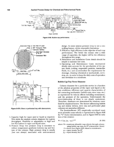
Figure 8-66, Bubble cap performance.
Downcomer Edge or Inlet Weir (if used)
/ ,Holes on 60° Triangular Pitch design. In some systems pressure drop is not a con-
trolling feature, within reasonable limitations.
3. Efficiency: high efficiency is the objective of each tray
Hole-Shell Clearonce performance. The better the contact over a wide
range of capacities, the higher will be the efficiency
throughout this range.
4. Fabrication and Installation Costs: details should be
simple to maintain low costs.
5. Operating and Maintenance Costs: mechanical
details must account for the peculiarities of the sys-
tem fluids (coking, suspended particles, immiscible
~i~,d Hole Area 3 k3” fluids, etc.) and accommodate the requirements for
’I’
Active Hole Area drainage, cleaning (chemical or mechanical), corro-
sion, etc., in order to keep the daily costs of operation
and downtime to a minimum.
Bubble-Capway Tower Diameter
Column diameter for a particular service is a function
of the physical properties of the vapor and liquid at the
tray conditions, efficiency and capacity characteristics of
the contacting mechanism (bubble trays, sieve trays, etc.)
as represented by velocity effects including entrainment,
and the pressure of the operation. Unfortunately the
interrelationship of these is not clearly understood.
Therefore, diameters are determined by relations corre-
lated by empirical factors. The factors influencing bubble
cap and similar devices, sieve tray and perforated plate
Figure 8-67A. Sieve or perforated tray with downcomers. columns are somewhat different.
The Souders-Brown [67] empirically correlated maxi-
mum allowable mass velocity is represented in Figure 8-82
for “C” Factor determination, and in Figure 8-83 for solu-
1. Capacity: high for vapor and/or liquid as required. tion of the relation:
This yields the smallest column diameter for a given
throughput. Flexibility or adaptability to high and w = c [p, (PL - PV)11’* (8-219)
low fluctuations in vapor and liquid rates. where W = maximum allowable mass velocity through column
2. Pressure Drop: low pressure drop is necessary to using bubble cap trays, lb/ft2 cross-section) (hour)
reduce temperature gradients between top and bot- C = factor from Figure 8-82 related to entrainment
tom of the column. High pressure drop is usually pv = vapor density, lbs/ft3
(but not always) associated with uneconomical p~ = liquid density, lbs/ft3