Page 141 - Applied Process Design For Chemical And Petrochemical Plants Volume II
P. 141

130                       Applied Process Design for Chemical and Petrochemical Plants

                                                              The “C” factor  is  determined at the  top  and  bottom
                                                             (or intermediate)  positions  of  the  column  in  order to
                                                            evaluate the point of maximum  required  diameter. The
                                                            “W rate obtained in this solution is the maximum allow-
                                                            able, and hence corresponds to the minimum acceptable
                                                            diameter for operation with  essentially no entrainment
                                                            carryover  from  plate  to  plate.  Normally  a  factor  of
                                                            “safety” or “ignorance” of  1.10 to 1.25 would be applied
                                                             (W divided by  1.10 to  1.25) if  irregularities in  capacity,
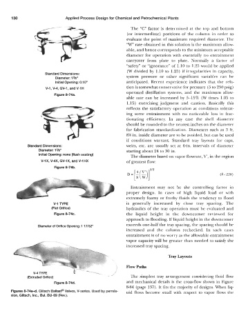
                      Standard Dimensions:                  system  pressure  or  other  significant  variables  can  be
                           Diameter: 17b”
                           Initial Opening: 0.10“           anticipated.  Recent  experience  indicates  that  the  rela-
                      V-1, V-4, GV-1, and V-1 H             tion is somewhat conservative for pressure (5 to 250 psig)
                                                            operated  distillation  systems, and  the  maximum  allow-
                           Figure 8-74a.
                                                            able  rate  can be  increased  by  5-15%  (W times  1.05 to
                                                             1.15)  exercising judgment  and  caution.  Basically  this
                                                            reflects  the  satisfactory operation  at conditions  tolerat-
                                                            ing  some  entrainment  with  no  noticeable  loss  in  frac-
                                                            tionating  efficiency.  In  any  case  the  shell  diameter
                                                            should be rounded to the nearest inches on the diameter
                                                            for fabrication  standardization.  Diameters  such  as  3  ft,
                                                            8% in. inside diameter are to be avoided, but can be used
                                                            if  conditions  warrant.  Standard  tray  layouts  for  caps,
              Standard Dimensions:                          weirs,  etc.  are usually  set at 6-in. intervals of  diameter
                   Diameter: 17N                            starting about 24 to 30 in.
                   Initial Opening: none (flush seating)
                                                              The diameter based on vapor flowrate,  V‘, in the region
                    V-lX, V-4X, GV-lX, and V-1 HX           of greatest flow:
                           Figure 8-74b.
                                                                        1/2
                                                             D=[:($)]                                   (8 - 220)


                                                              Entrainment  may  not  be  the  controlling  factor  in
                                                            proper  design.  In  cases  of  high  liquid  load  or  with
                                                            extremely foamy or frothy fluids  the  tendency to  flood
                          V-1 TYPE                          is  generally  increased  by  close  tray  spacing.  The
                         (Fiat Orifice)                     hydraulics of  the tray operation  must be  evaluated and
                           Figure 8-74c.                    the  liquid  height  in  the  downcomer  reviewed  for
                                                            approach to flooding. If liquid height in the downcomer
                                                            exceeds one-half the tray spacing, the spacing should be
                   Diameter of Orifice Opening: 1 17/32“
                                                            increased  and  the  column  rechecked.  In  such  cases
                                                            entrainment is of no worry as the allowable entrainment
                                                            vapor capacity will be greater than needed  to satisfy the
                                                            increased tray spacing.

                                                                                Tray Layouts


                                                            Flow Paths

              (Extruded Orifice)                              The simplest tray  arrangement  considering  fluid flow
                           Figure 8-74d.                    and mechanical  details is  the  cross-flow shown in  Figure
                                                            8-84 (page 137). It fits the majority of designs. When liq-
      Figures 8-74a-d. Glitsch Ballast@ Valves, V-series. Used by permis-   uid  flows become  small with  respect  to  vapor flows  the
      sion, Glitsch, Inc., Bul. BU-69 (Rev.).
   136   137   138   139   140   141   142   143   144   145   146