
Page 146 - Applied Process Design For Chemical And Petrochemical Plants Volume II
P. 146
Distillation
For Petroleum Column, Multiply
100
Surface Tension, Dynes Icm.
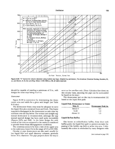
Figure 8-82. "C" factors for column diameter using bubble cap trays. Adapted by permission, The American Chemical Society, Sol Jders, M.,
Jr., and Brown, G. G. Ind. and Eng, Chem. V. 26 (1 934), p. 98, all rights reserved.
should be capable of traveling a minimum of 2 in., with serve as the overflow weir. (Note: Calculate flow down on
designs for some trays being 4 to 6 in. this circular basis, assuming the pipe can be surrounded
by liquid on the my.)
DaVnGOmer The downcomer seal on the tray is recommended [5]
Figure 8-100 is convenient for determining the down- based on the liquid flow path:
comer area and width for a given weir length (see Table
8-16 also). Liquid Path, Downcomer to Outlet
The downcomer from a tray must be adequate to carry weir, ft Downcomer Seal, in.
the liquid flow plus entrained foam and froth. This foamy Below 5 0.5
material is disengaged in the downcomer as only clear liq- 5-1 0 1 .o
uid flows onto the tray below. The vertical and straight seg- Above 10 1.5
mental downcomer is recommended, although the seg-
mental tapered design has been used quite successfully Liquid By-Pass Baffles
(Figures 8-67a and 8-86). In the latter design the wide
mouth of the inlet as compared to the outlet is considered Also known as redistribution baffles, these short stub
to provide better foam disengagement conditions. baMes guide the liquid flow path to prevent excessive by-
The consensus seems to be that a ratio of the upper area passing of the bubble cap field or active tray area. Unfor-
to the outlet area (lower) be in the range of L5 to 2.0 [190]. tunately this action is overlooked by many designers with
Circular or pipe downcomers are also used, usually for
low liquid flow and small diameter columns, generally (fat continwd on page 154
below 18 in. diameter. The pipe projects above the tray to