
Page 142 - Applied Process Design For Chemical And Petrochemical Plants Volume II
P. 142
Distillation 131
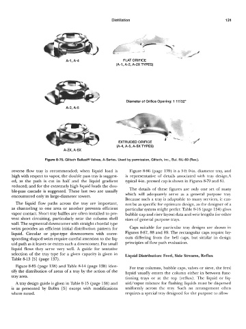
A-1 , A-4 FLAT ORIFICE
(A-1 , A-2, A-2X TYPES)
Diameter of Orifice Opening: 1 17/32"
A-2, A-5
EXTRUDED ORIFICE
(A-4, A-5, A-5X TYPES)
A-W, A-5X
Figure 8-75. Glitsch Ballast@ Valves, A-Series. Used by permission, Glitsch, Inc., Bul. BU-69 (Rev.).
reverse flow tray is recommended; when liquid load is Figure 8-86 (page 139) is a 3-ft 0-in. diameter tray, and
high with respect to vapor, the double pass tray is suggest- is representative of details associated with tray design.A
ed, as the path is cut in half and the liquid gradient typical 4in. pressed cap is shown in Figures 879 and 81.
reduced; and for the extremely high liquid loads the dou-
ble-pass cascade is suggested. These last two are usually The details of these figures are only one set of many
encountered only in largediameter towers. which will adequately serve as a general purpose tray.
Because such a tray is adaptable to many services, it can-
The liquid flow paths across the tray are important, not be as specific for optimum design, as the designer of a
as channeling to one area or another prevents efficient particular system might prefer. Table 8-16 (page 154) gives
vapor contact. Short tray baffles are often installed to pre- bubble cap and riser layout data and weir lengths for other
vent short circuiting, particularly near the column shell sizes of general purpose trays.
wall. The segmental downcomer with straight chordal type
weirs provides an efficient initial distribution pattern for Caps suitable for particular tray designs are shown in
liquid. Circular or pipe-type downcomers with corre- Figures 887, 88 and 89. The rectangular caps require lay-
sponding shaped weirs require careful attention to the liq- outs differing from the bell caps, but similar in design
uid path as it leaves or enters such a downcomer. For small principles of flow path evaluation.
liquid flows they serve very well. A guide for tentative
selection of the tray type for a given capacity is given in Liquid Distribution: Feed, Side Streams, Reflux
Table 8-13 [5] (page 137).
Figure 8-85 (page 138) and Table 8-14 (page 138) iden- For tray columns, bubble caps, valves or sieve, the feed
tify the distribution of areas of a tray by the action of the liquid usually enters the column either in between func-
tray area. tioning trays or at the top (reflux). The liquid or liq-
A tray design guide is given in Table 8-15 (page 138) and uid/vapor mixture for flashing liquids must be dispersed
is as presented by Bolles [5] except with modifications uniformly across the tray. Such an arrangement often
where noted. requires a special tray designed for the purpose to allow