
Page 145 - Applied Process Design For Chemical And Petrochemical Plants Volume II
P. 145
134 Applied Process Design for Chemical and Petrochemical Plants
Cap Pitch Center to Center
Cap sizes 2-in., 3-in., and 4in.: recommended cap lane
distance of 1% in. (with Min. minimum, l%inch maxi-
mum) plus cap outside diameter.
For cap sizes of 6 and 8 in.: recommended cap lane dis-
tance of 1% in. (1%-in. minimum, 2?4in. maximum) plus
SPd cap outside diameter.
'Weld
Weirs
I Figure 8-100 is convenient for arriving at weir lengths
' %"a x 2%" Hex Head
relative to their effect on segmental downcomers.
metal washer
-- (a) Inlet
These contribute to the uniform distribution of liquid
as it enters the tray hm the downcomer. There are about
as many tray designs without weirs as with them. The
downcomer without inlet weir tends to maintain uniform
liquid distribution itself. The tray design with recessed seal
14 ga. cap
pan ensures against vapor backflow into the downcomer,
but this is seldom necessary. It is not recommended for
fluids that are dirty or tend to foul surfaces. The inlet weir
is objectionable for the same reason.
The first row of caps next to the weir or inlet downcomer
must be set back far enough to prevent bubbling into the
downcomer. The inlet weir prevents this, although it can be
Detail of Pressed properly handled by leaving about 3 in. between inlet down-
Cap and Riser comer and the nearest face of the first row of caps.
Scale: 314" = 1 I'
The height of an inlet weir, ifused, should be 1 to 1% in.
above the top of the slots of the bubble caps when
installed on the tray.
If inlet weirs are used they should have at least two slots
dots
%in. by 1-in. flush with the tray floor to aid in flushing out
any trapped sediment or other material. There should also
be weep or drain holes below the downcomer to drain the
weir seal area. The size should be set by the type of service,
but a minimum of %in. is recommended.
Detail of Slots (b) Outlet
Pressed Cap
=
scale: I" 1" These are necessary to maintain seal on the tray, thus
ensuring bubbling of vapors through liquid. The lower the
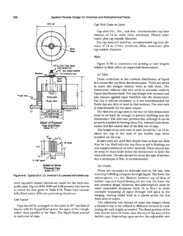
Figure 881. Typical 3Mn. I.D. (nominal 4 in.) pressed bell bubble cap.
submergence, i.e., the distance between top of slots of
bubble caps and liquid flowing on the tray, the lower the
once cap-pitch master layouts are made for the sizes nor- tray pressure drops. However, this submergence must be
mally used. Figures 8-92-8-99 and 8-86 present tray layouts some reasonable minimum value (V, to %in.) to avoid
to match the data given in Table 8-16. These have success-
fully fitted many different processing situations. excessive by-passing of vapor through void spots in the
surging, moving liquid body as it travels across the tray
Cap Laput from inlet to outlet
The adjustable weir feature of many tray designs allows
Caps should be arranged on the plate in 60" equilateral a standard tray to be utilized in different services by read-
layout, with the liquid flowing into the apex of the triangle justing the weir height as needed. The fmed portion of the
rather than parallel to the base. The liquid flows normal weir should never be lower than the top of the slots of the
to each row of caps. bubble caps. Depending upon service, the adjustable weir