
Page 149 - Applied Process Design For Chemical And Petrochemical Plants Volume II
P. 149
138 Applied Process Design for Chemical and Petrochemical Plants
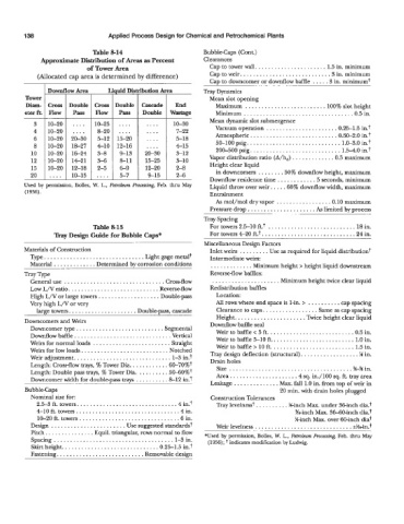
Table 8-14 Bubblecaps (Cont.)
Approximate Distribution of Areas as Percent Clearances
of Tower Area Cap to tower wall. ..................... 1.5 in. minimum
(Allocated cap area is determined by difference) Cap to weir. .......................... .3 in. minimum
Cap to downcomer or downflow baffle .... .3 in. minimum+
.
Ii uid Distribution Area
Downflow Area +- Tray Dynamics ... ._ - .......... -
Tower I I Mean slot opening
Diam- cross Double Cascade End Maximum ......................... 100% slot height
eter ft. Flow Pass I Double Wastage Minimum ................................. .0.5 in.
~. Mean dynamic slot submergence
3 10-20 .... 10-25 10-30
4 10-20 .... 8-20 7-22 Vacuum operation ..................... .0.25-1.5 in.t
Atmospheric ..........................
6 5-12 5-1 8 30-100 psig. ............................ .0.50-2.0 in.t
1.0-3.0 in.?
8 410 4-15 200-500 psig ............................
10 3-8 3-12 1.5-4.0 in.?
12 3-6 3-10 Vapor distribution ratio (A/hc) ............ .0.5 maximum
15 2-5 2-8 Height clear liquid
20 .... 10-15 .... 2-6 in downcomers ....... .50% downflow height, maximum
Downflow residence time ........... .5 seconds, minimum
Used by permission, Bolles, W. L., Petrohm fiocessing, Feb. thru May Liquid throw over weir. ... .60% downflow width, maximum
(1956). Entrainment
As mol/mol dry vapor ................. 0.10 maximum
Pressure drop ..................... As limited by process
.....
Tray Spacing
Table 8-15 For towers 2.5-10 ft.t ........................... 18 in.
Tray Design Guide for Bubble Caps* For towers 4-20 ft.t ............................ .24 in.
....... Miscellaneous Design Factors
Materials of Construction Inlet weirs ......... Use as required for liquid distributiont
Type. .............................. Light gage metalt Intermediate weirs:
Material ............. Determined by corrosion conditions ............. Minimum height > height liquid downstream
Tray Type Reverse-flow baffles:
General use ............................... Crossflow ..................... Minimum height twice clear liquid
Low L/V ratio. ........................... Reverseflow Redistribution baffles
High L/V or large towers ................... Double-pass Location:
Very high L/V or very All rows where end space is 1-in. > .......... cap spacing
large towers. .................... Doublepass, cascade Clearance to caps. ................ Same as cap spacing
Height. ..................... Twice height clear liquid
Downcomers and Weirs Downflow baffle seal
Downcomer type ........................... Segmental
Downflow baffle .............................. Vertical Weir to baffle < 5 ft. ......................... .0.5 in.
Weirs for normal loads ........................ Straight Weir to baffle 5-10 ft.. ........................ 1.0 in.
Weirs for low loads. .......................... Notched Weir to baffle > 10 ft. ......................... 1.5 in.
Weir adjustment. ............................. 1-3 in.? Tray design deflection (structural). ................. ?4 in.
Drain holes
Length: Cross-flow trays, % Tower Dia. .......... .60-70%t Size ...................................... %-% in.
Length: Double pass trays, % Tower Dia. ........ .5060%t Area. ................... .4 sq. in./100 sq. ft. tray area
Downcomer width for doublepass trays ......... .8-12 in.t
Leakage .............. Max. fall 1.0 in. from top of weir in
Bubblecaps 20 min. with drain holes plugged
Nominal size for: Construction Tolerances
2.5-3 ft. towers. ............................. .4 in.+ Tray levelness+. ......... %inch Max. under 36-inch dia.t
4-10 ft. towers ............................... .4 in. %inch Max. 36-60-inch dia.t
10-20 ft. towers .............................. .6 in. %-inch Max. over 60-inch diat
Design ....................... Use suggested standards? Weir levelness .............................. &ein.t
- ..... _-
Pitch. .............. Equil. triangular, rows normal to flow *Used by permission, Bolles, W. L., Petmleum hcessing, Feb. thru May
Spacing ..................................... 1-3in. (1956) ; t indicates modification by Ludwig.
Skirt height. ............................. 0.25-1.3 in.+
Fastening. .......................... Removable design