
Page 144 - Applied Process Design For Chemical And Petrochemical Plants Volume II
P. 144
Distillation 133
PL-VALVE
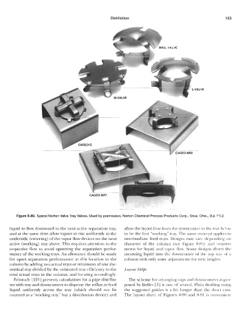
Figure 8-80. Typical Norton Valve Tray Valves. Used by permission, Norton Chemical Process Products Corp., Stow, Ohio., Bul. FT-2.
liquid to flow downward to the next active separation tray, allow the liquid flow from the downcomer to the tray bclow
and at the same time allow vapors to rise uniformly to the to be the first “working” tray. The same concept applies to
underside (entering) of the vapor flow devices on the next intermediate feed trays. Designs may vary depending on
active (working) tray above. This requires attention to the diameter of the column (see Figure 8-84) and require-
respective flow to avoid upsetting the separation perfor- ments for liquid and vapor flow. Some designs direct the
mance of the working trays. An allowance should be made incoming liquid into the downcomer of the top tray of a
for upset separation performance at this location in the column with only some adjustments for weir heights.
column by adding two actual trays or minimum of one the-
oretical tray divided by the estimated tray efficiency to the Layout Helps
total actual trays in the column, and locating accordingly.
Feintuch [221] presents calculations for a pipe distribu- The scheme for arranging caps and downcomers as pro-
tor with tray and downcomers to disperse the reflux or feed posed by Bolles [5] is one of several. Plain drafting using
liquid uniformly across the tray (which should not be the suggested guides is a bit longer than the short cuts.
counted as a “working tray,” but a distribution device) and The layout sheet of Figures 8-90 and 8-91 is convenient