
Page 213 - Applied Process Design For Chemical And Petrochemical Plants Volume II
P. 213
202 Applied Process Design for Chemical and Petrochemical Plants
From Figure 8-12'7 read friction factor: This is satisfactory, because it is less than 50% of the tray
f = 0.018 approximate extrapolation spacing of 24in. Therefore, the tray appears to have ade-
Area of downcomer flow segment: quate liquid handling capacity. No hole blanking strips
required.
From Appendix Tables: A = d2(coef) (8-301)
Perforated Plates Without Downcomers
From Figure 8-100:
At 77% weir times tower diameter, then downcomer Perforated plates without downcomers have only
area = 12.4% of tower area, or 18% of tower diameter is recently been included in commercial equipment. The
downcomer width (depth, i.e. weir to wall = 0.18 (10.5) = data for rating the performance is not adequately covered
1.89 ft for one downcomer). Then, net free area between in the literature, since the present developments in indus-
weirs = 10.5 - 1.89 - 1.89 = 6.72 ft trial equipment have not been released. The information
included here is based only on available data and experi-
ence, yet it may serve as a basis for rating, because the
f (vi l2 lfp
Gradient, A', = basic nature of the contact is quite analogous to the sieve
g RH tray. The limits of performance are not well defined;
therefore the methods outlined cannot be considered
firm. However, they are adequate for many applications
and as the basis for further study.
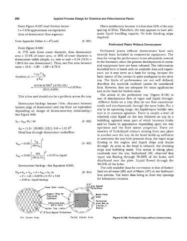
The action of the perforated tray (Figure 8-146) is
This is low and should not be a problem across the tray.
one of simultaneous flow of vapor and liquid through-
Downcomer backup: Assume 1 %-in. clearance between different holes on a tray; they do not flow countercur-
bottom edge of downcomer and tray floor (or equivalent rently and simultaneously through the same holes. For a
depending on design of downcomer-tray relationship.) tray in its operating range, the liquid-vapor bubble mix-
See Figure 8-63. ture is in constant agitation. There is usually a level of
relatively clear liquid on the tray followed on top by a
Ad = hdcl Wl/144 (8 - 302) bubbling, agitated mass, part of which becomes frothy
and/or foamy in appearance depending upon the tray
= (1.5) [(8.085) (12)]/144 = 1.01 ft2 operation and the fluid system properties. There are
Head loss through downcomer underflow: wavelets of froth-liquid mixture moving from one place
to another over the tray. As the head builds up sufficient
to overcome the tray hole pressure drop, the vapor stops
(8 - 303) flowing in the region and liquid drips and drains
through. As soon as the head is reduced, the draining
stops and bubbling starts. This action is taking place
randomly over the tray. Sutherland [69] observed that
hdu = (0.03) [ 504 = 0.747 in. liquid
100 (1.01) vapor was flowing through 70-90% of the holes, well
distributed over the plate. Liquid flowed through the
Downcomer backup : See Equation 8-245; 30-10% of the holes.
The only available data for correlation is that of Suther-
+
Hd = h, + h, A + hdu + ht, in. (8 - 304) land on air-water [69] and of Myers [4'7] on two hydrocar-
= 2 -I- 1.45 + 0.0278 + 0.747 + 3.98 bon systems. The latter data being at close tray spacings
= 8.20 in. liquid backup for laboratory columns.
fL3"
_-I ,-Area Beyond
,Tower Shell Inside,
Support Ring for
Trav.lnside 1
erforated Are
60'A Pitch
'Active Tray Limits/
2"-3" Areo Beyond Perforations
Full Column Areo Partial Column Areo Figure 8-146. Perforated trays without downcorners.