
Page 209 - Applied Process Design For Chemical And Petrochemical Plants Volume II
P. 209
198 Applied Process Design for Chemical and Petrochemical Plants
Because vom (pV)lI2 = 12.5 is less than the assumed
value of 13, the 13 will be used. hd, = 0.56 - = 0.56 = 0.312 in liquid
[ 44gLhd))l [ 449 22.1 (0.065) ] across restriction
Maximum Hob Velocity at Rood Conditions
5. Dry tray pressure drop
Assume F, = vo (pv) = 20 max.
hdt = 0.003 (17)' (62.3/85) (1 - (0.128)'/(0.78)' = 1.04
in. liquid
Dry tray pressure drop
=O.O03F: (y) 6. Effective head
(l-fl2)/C;
h,l = 1.52 in.
he = 1.4 in. liquid for F, > 14, Figure 8-130
= 0.003 (20)2 (62.3/85) (1 - (0.128)2)/(0.78)2 7. Total wet tray pressure drop
= 1.44 in. liquid
h, = 1.04 + 1.4 = 2.44 in. liquid
Effective head, he
8. Total tower pressure drop for 45 trays:
= 1.4 in. liquid, for F, > 14 and h,l = 1.5 (2.44) (45) 83 + 83
A P (tower) = 1728 cu. in./cu. ft. ( 2 ) = 5.33 psi
Total wet tray pressure drop, ht = 1.44 + 1.4 = 2.84 inch-
es liquid
An actual operating tower measured 5 psi k. It is
Liquid Back-up OT Height in Downcomer satisfactory to average the conditions for top and
bottom of tower when flows do not vary significant-
Hd = ht + (hw + h,) + A +hd ly. Otherwise, parallel determinations must be car-
Hd = 2.84 + 1.5 + 0 + 0 (assumed, to be confirmed) ried through for top and bottom (and even feed in
Hd = 4.34 in. liquid some cases) conditions.
9. Number of holes required
The limit on Hd for flooding is St/2 = 9/2 = 4.5 in. Hole size selected = %in.
Therefore F, = 20 appears to be close to minimum. Hole spacing or pitch = Ihin.
From Figure 8-144, Holedin.:! plate area = 4.62
Design Hob VelociQ Area of a %win. hole = 0.0276 in.2
Select a velocity represented by F, factor between mini-
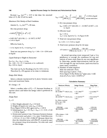
mum and maximum limits. Calculation Summary
- - - - ___ _--
20 > Design > 13 Maximum Velocity Design Velociq weep Point
- - - --- - _-
Select a median value of F, = 17, because freedom to F, = 20 17 13
operate above and below the design value is preferred in vo top =
this case. 20/(0.582)'/* = 26.2 ft./sec. = 17/(.582)'/* = 13 (0.582)'12
= 22.3 = 17
V, Bot. =
Design Basis 20/(0.674)1/2 = 24.4 ft./sec. = 17/(0.674)1/2 = 13/(0.674)'/'
= 20.7 = 15.8
F, = 17 No. Holes required
CFS at top = 3.23
1. Weir Height selected = h, = 1.0 inch No. holes =
2. Height of liquid over weir, how = 0.52 in.
From Figure 8-104 at 22.1 gpm and 1, = 1.62 ft 5.23 (144) = 1040 i 5.23 (144) - 3.23 (144)
3. Submergence, hsl = (0 (h,,) + how = (1) (1.0) + 0.52 26.2 (0.0276) 22.3 (0.0276) 17 (0.0276)
= 1.52 in. liquid = 1223 = 1605
4. Downcomer pressure loss. Clearance between bottom CFS at bottom = 5.58
of downcomer and plate = 1-in. max. Underflow area No. holes =
= (9.5 in.) (1 in.)/144 = 0.065 ft2. Because this is less
than the downflow area (of 0.334 ft2), it must be used 5.58 (144) 1195 - 5.58 (144) h 5.58 (144)
for pressure drop determination. No inlet weir used 24.4 (0.0276) 20.7 (0.0276) 13.8 (0.0276)
on this design. = 1410 = 1845