
Page 210 - Applied Process Design For Chemical And Petrochemical Plants Volume II
P. 210
Distillation 199
The selected design F, = 17 gives the number of Height of chord = 13.25 - (15 - 3.6 - 3) = 4.85
holes to operate at these conditions. Note that the h/D = 4.85/26.5 = 0.183
values of 1223 and 1410 holes for the top and bot-
tom respectively indicated operations somewhat Area = 0.0984 (26.5)‘ = 69.1 in.’
closer to the tower maximum than to the weep Area of circle (2) = n (26.3)2 = 552 in.2
point. This usually insures as good an efficiency as is
obtainable for a given system. It may limit the flexi- Area available for holes = 552 - 113.2 - 69.1 = 369.7 in.2
bility of the tower, since there will not be enough Area required for holes = (1410)/4.62 holes/im2 = 305
holes to operate down to the weep point at the given in.’
design flow rates.
On the other hand the tower should be able to Actually not all of the tray needs to be drilled. Howev-
operate at changing vapor and liquid loads without er, the location of “dead” or unperforated areas must be
serious upset. In this type of tray the designer has a carefully selected, preferable next to weirs. 4 special
selection of holes, in this case: For the top select punching (or drilling) arrangement for the holes can run
1,100 to 1,500; for the bottoms, select 1,300 to 1,750, the cost of the trays quite high. It will probably be prefer-
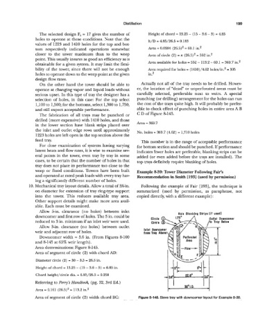
and still expect acceptable performance. able to check effect of punching holes in entire area A B
The fabrication of all trays may be punched or C D of Figure &145.
drilled (more expensive) with 1410 holes, and those
in the lower section have blank strips placed over Area = 369.7
the inlet and outlet edge rows until approximately No. holes = 369.7 (4.62) = 1,710 holes
1223 holes are left open in the top section above the
feed tray. This number is in the range of acceptable performance
For close examination of systems having varying for bottom section and should be punched. If performance
latent heats and flow rates, it is wise to examine sev- indicates fewer holes are preferable, blanking strips can be
eral points in the tower, even tray by tray in some added (or even added before the trays are installed). The
cases, to be certain that the number of holes in that top trays definitely require blanking of holes.
tray does not place its performance too close to the
weep or flood conditions. Towers have been built Example 8-39: Tower Diameter Following Fair’s
and operated at rated peak loads with every tray hav- Recommendation in Smith [1931 (used by permission)
ing a significantly different number of holes.
10. Mechanical tray layout details. Allow a total of 3%n. Following the example of Fair [193], the technique is
on diameter for extension of tray ring-type support summarized (used by permission, as paraphrase, not
into the tower. This reduces available tray area. copied directly, with a different example) :
Other support details might make more area avail-
able. Each must be examined.
Allow 5-in. clearance (no holes) between inlet
downcomer and first row of holes. The 5 in. could be Hole Blanking Strips (if used)
flct Downcorner
reduced to 3 in. minimum if an inlet weir were used.
Allow %in. clearance (no holes) between outlet
weir and adjacent row of holes. inlet
from
Downcomer width = 3.6 in. (From Figures 8-100
and 8-145 at 65% weir length).
Area determinations: Figure 8-145.
Area of segment of circle (2) with chord AD:
Diameter circle (2) = 30 - 3.5 = 26.3 in.
Height of chord = 13.23 - (15 - 3.6 - 5) = 6.85 in.
Chord height/circle dia. = 6.83/26.5 = 0.258 w
Referring to Perry’s Handbook, (pg. 32, 3rd Ed.)
1.
Area = 0.161 (26.5)2 = 113.2 in2 30” D.
Area of segment of circle (2) width chord BC: Figure 8-145. Sieve tray with downcomer layout for Example 8-38.