
Page 206 - Applied Process Design For Chemical And Petrochemical Plants Volume II
P. 206
Distillation 1 95
as drops dispersed in the gas), which is usually in vacuum
and low liquid-rate service [213].
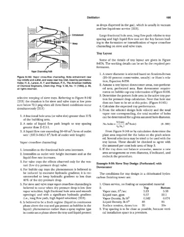
Entrainment Large fractional hole area, long flow path relative to tray
spacing and high liquid flow rate are the key factors lead-
Weep ing to the formation or intensification of vapor cross-flow
channeling on sieve and valve trays.
Tray Layout
Some of the details of tray layout are given in Figure
8-67A. The working details can be set by the required per-
formance.
Vapor Channelkg Path
1. A tower diameter is selected based on Souders-Brown
Figure 8-142. Vapor cross-flow channeling. Note entrainment near (20-50 percent conservative, usually) or Hunt's rela-
tray middle and outlet, and weep near tray inlet. Used by permission, tion, Equation &250.
Kister, H. Z., Larson, K. F. and Madsen, I? E., The American Institute
of Chemical Engineers, Chem Eng. Prog. V. 88, No. 11 (1992), p. 86, 2. Assume a tray layout: downcomer areas, non-perforat-
all rights reserved. ed area; perforated area. Base downcomer require
ments on bubble cap tray information of Figure 81 00.
3. Determine the percent hole area in the active tray por-
selective weeping of sieve trays. Referring to Figure 8-142 tion for pressure drop calculation. Note that hole size
[213] the situation is for sieve and valve trays at low pres- does not have to be set at this point. (Figure 8-143.)
sure below 72.5 psig when all three listed conditions occur 4. Calculate the expected tray performance.
simultaneously [213] :
5. From the selected design hole velocity and the total
vapor rate corresponding, the total number of holes
I. A fractional hole area (or valve slot) greater than 11% can be determined for a gi\7en assumed hole diameter.
of the bubbling area.
2.A ratio of liquid flow path length to tray spacing (8 - 300)
greater than 2-231.
3. A liquid flow rate exceeding 50-60 m3/hr-m of outlet From Figure 8-144 or by calculation determine the
weir (537.9-645.5 ft3/hr-ft of outlet weir length) plate area required for the holes on the pitch select-
ed. Several selections may be tried to be used with the
Vapor cross-flow channeling: tray layout. These should be checked to agree with
the assumed per cent hole area of Step 3.
1. Intensifies as the fractional hole area increases. 6. If the tray does not balance area-wise, assume a new
2. Intensifies as outlet weir height increases and as the area arrangement or even diameter, if indicated, and
liquid flo~7 rate increases. recheck the procedure.
3. For valve trays the effects observed only for the ven-
turi (low dry pressure drop) valve. Example 8-38: Sieve Tray Design (Perforated) with
Downcomer
4. For bubble cap trays the phenomenon is believed to
be induced by excessive hydraulic gradient; it is rec- The conditions for tray design in a chlorinated hydro-
ommended to keep hydraulic gradient to less than carbon finishing tower are:
40% of the dry pressure drop.
5. For sieve and valve trays vapor cross-flow channeling is 1. Clean service, no fouling or suspended material
believed to occur when dry pressure drop is low (low 2. TOP Bottom
vapor velocities, high fractional hole area and smooth Vapor rate, ft"/sec 5.23 5.58
openings) and with a significant hydraulic gradient Liquid rate, gpm 9.57 22.1
(i.e., long flow path, high liquid velocities) [213]. Vapor Density, lb/ft3 0.582 0.674
6. Is believed to be a froth regime (liquid in continuous Liquid Density, lb ft3 83 85
phase above the tray and gas present as bubbles in the Surface tension, dynes/cm 20 20+
liquid) phenomenon rather than a spray regime (gas 3. Tray spacing is to be close as possible, because verti-
in continuous phase above the tray and liquid present cal installation space is a premium.