
Page 224 - Applied Process Design For Chemical And Petrochemical Plants Volume II
P. 224
Distillation 21 3
I
V Load
Tower Area
System Limit
Flooding
Downcomer
Backup
Downcomer Flooding
Two-Phase Figure 8-152A. Mechanical performance correla-
tions for high-pressure fractionation trays. Used
by permission, Capps, R. W., The American Insti-
Flowflower Area tute of Chemical Engineers, Chem. Eng. frog. V.
Note: Drawing not to scale. 89, No. 3, (1993), p. 35, all rights reserved.
‘t\
V Load Downcomer
Two-Phase
Tower Area
Flooding
%
Downcomer
Backup
Flooding
Figure 8-1528. Mechanical performance correla-
tions for vacuum fractionation trays. Used by
permission, Capps, R. W., The American Institute
Flowflower Area of Chemical Engineers, Chem. Eng. frog., V. 89,
Note: Drawing not to scale. No. 3, (1993), p. 35, all rights reserved.
AT = tower area, ft2
CT = capacity factor, based on tower area, ft/s Segmental
CTflood = capacity factor at flood, ft/s baffle-
DT = tower diameter, ft
Fflood = flood factor, dimensionless
L/V = internal reflux ratio, dimensionless
m,,, = vapor rate, lb/s
mVapflood = vapor rate at flood, lb/s
pvap = vapor density, lb/ft3
pliq = liquid density, lb/ft3
S = tray spacing, in.
Vload = vapor load, corrected for density, ft3/s
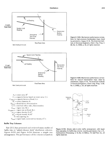
Baffle Tray Columns
Fair [211] has presented and reviewed many studies of
baffle tray, or “splash/shower deck distillation columns. Figure 8-153. Simple side-to-side baffle arrangement, with liquid
Figures 8-153 and Figure 8-154 illustrate a simple tray flow cascades, for baffle tray column. Used by permission, Fair, J. R.,
Hydrocarbon Processing, V. 72, No. 5 (1 993) p. 75, Gulf Pub. Co., all
arrangement. The performance of the column is based on rights reserved.