Page 225 - Applied Process Design For Chemical And Petrochemical Plants Volume II
P. 225

21 4                      Applied Process Design for Chemical and Petrochemical Plants

                                                                        90
                                                                        80
                                                                        70
                                                                      c.
                                                                       $
                                                                      860
                                                                       E
                                                                       €50
                                                                       ci
                                                                      g40
                                                                       92
                                                                        30
                                                                       2
                                                                      a
                                                                        20
                                                                        10
                                                                         0
                                                                          0   1   2   3   4   5   6
                                                                                      ZF
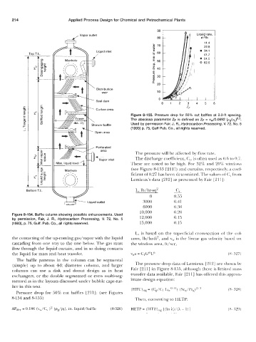
                                                             Figure 8-155.  Pressure drop for  50%  cut  baffles at 2.04 spacing.
                                                            The abscissa parameter ZF is defined as ZF = vw/0.0692 (~s/pl)O.~.
                                                             Used by permission Fair, J. R., Hydrocarbon Processing, V.  72. No. 5
                                                             (1 993) p. 75, Gulf Pub. Co., all rights reserved.


                                                               The pressure will be affected by  flow rate.
                                                               The discharge coefficient, C,, is often used as 0.6 to 0.7.
                                                             These are noted  to be  high. For 32% and 20% windows
                                                             (see Figure 8-153 [211]) and curtains, respectively, a coef-
                                                             ficient of 0.27 has been determined. The values of C,  from
                                                             Lemieux's data [212] as presented by Fair [211]:


             Bottom T.L.                                       L, lb/hr-sq2     ~  c,.
                                                                     0          0.55
                              l  +  p    Liquid outlet            3000          0.41
                                                                  6000          0.30
                                                                 10,000         0.20
       Figure 8-154.  Baffle column showing possible enhancements. Used   12,000   0.15
       by  permission,  Fair,  J.  R.,  Hydrocarbon  Processing, V.  72,  No.  5
       (1993), p. 75, Gulf. Pub. Co., all rights reserved.       15,000         0.15

                                                               L, is  based  on  the superficial  cross-section of  the  col-
       the contacting of the up-coming gas/vapor with the liquid   umn, lb/hr-f(',  and v,~ is the linear gas velocity based on
       cascading from one tray to the one below. The gas must   the window area, ft/sec,
       flow through the liquid curtain, and in so doing contacts
       the liquid for mass and heat transfer.                vwa = C1G"'L"                               (8 - 327)
         The baffle  patterns  in  the  column  can  be  segmental
       (simple) up  to  about  4ft diameter  column,  and  larger   The pressure drop data of Lemieux [212] are shown by
       columns  can  use  a  disk  and  donut  design  as  in  heat   Fair  [211] in Figure 8-155, although there is limited mass
       exchangers, or the double segmented  or even multi-seg-   transfer data available, Fair [211] has offered this approx-
       mented as in the layouts discussed under bubble caps ear-   imate design equation:
       lier in this text.
                                                             (HTU),,  = (C,/C,  L~,co~") (ScK/I'rK)''''   (8- :32x)
         Pressure  drop for 50% cut baffles  [211]:  (see Figures
       8-154 and 8-155)                                        Then, converting to HETP:

       Lipdry = 0.186 (v,,/c,  )2 (&/PI),  in. liquid/baffle   (8-326)
   220   221   222   223   224   225   226   227   228   229   230