
Page 221 - Applied Process Design For Chemical And Petrochemical Plants Volume II
P. 221
21 0 Applied Process Design for Chemical and Petrochemical Plants
Example: 8-41: Procedure for Calculating Valve Tray
Pressure Drop (after Klein [201])
For a venturi type tray, assume the following conditions:
Vapor flow: = 50,000 lb/hr = G
Liquid flow: = 205 gpm = Q
pv = 1.91 lb/ft3
t I I I I i
0.0 0.5 1 .0 1.5 2.0 2.5 pi = 31.0 lb/ft3
Fw = v v%,ftk .d%@ L,,; = 55 in.
hw = 3 in.
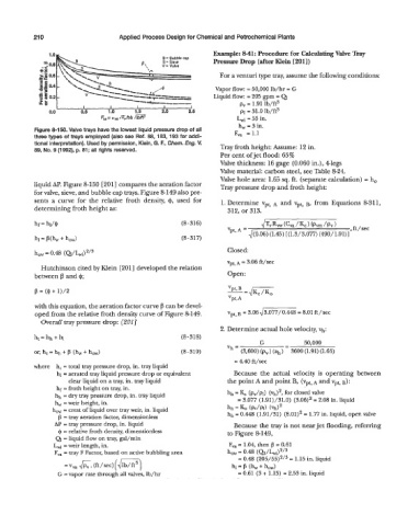
Figure 8-150. Valve trays have the lowest liquid pressure drop of all F, = 1.1
three types of trays employed (also see Ref. 88, 183, 193 for addi-
tional interpretation). Used by permission, Klein, G. F., Chem. Eng. V. Tray froth height: Assume: 12 in.
89, No. 9 (1992), p. 81; all rights reserved.
Per cent ofjet flood: 65%
Valve thickness: 16 gage (0.060 in.), 4legs
Valve material: carbon steel, see Table 8-24.
Valve hole area: 1.63 sq. ft. (separate calculation) = h,
liquid AP. Figure 8-150 [201] compares the aeration factor Tray pressure drop and froth height:
for valve, sieve, and bubble cap trays. Figure 8-149 also pre-
sents a curve for the relative froth density, $, used for 1. Determine vpt, A and vpt, B, from Equations 8-311,
determining froth height as: 312, or 313.
hf = hi/@ (8-316) &Rw(C,/Kc) (Pvm/Pv)
Vpt, A = , ft / sec
d(0.06) (1.45) [(1.3/3.077) (490/1.91)]
h, = 0.48 (Q/b) 'I3 Closed:
vpt, A = 3.06 ft/sec
Hutchinson cited by Klein [201] developed the relation
between p and 4; Open:
with this equation, the aeration factor curve f3 can be devel-
=
oped from the relative froth density curve of Figure 8-149. vpt,~ 3.064-= 8.0lft/sec
Overall tray pressure drop: [201]
2. Determine actual hole velocity, Vh:
ht = hh + hl (8-318)
G - 50,000
-
(3,600) (p,) (ah) 3600 (1.91) (1.65)
Vh a
= 4.40 ft/sec
where h, = total tray pressure drop, in. tray liquid
hl = aerated tray liquid pressure drop or equivalent Because the actual velocity is operating between
clear liquid on a tray, in. tray liquid the point A and point B, (vpt, A and vpt, B):
hf = froth height on tray, in.
hh = dry tray pressure drop, in. tray liquid hh = & (p,/pl) (Vh)', for closed Valve
h, =weir height, in. = 3.077 (1.91)/31.0) (3.06)2 = 2.08 in. liquid
how = crest of liquid over tray weir, in. liquid hh = (pv/Pl) (Vh)'
P = tray aeration factor, dimensionless hh = 0.448 (1.91/31) (8.01)' = 1.77 in. liquid, open valve
AP = tray pressure drop, in. liquid Because the tray is not near jet flooding, referring
Q = relative froth density, dimensionless to Figure 8-149,
Q = liquid flow on tray, gal/min
hi = weir length, in. F, = 1.04, then p = 0.61
Fva = tray F Factor, based on active bubbling area how = 0.48 (Q/h)2'3
= 0.48 (20?i/55)2/3 = 1.15 in. liquid
= vya ?K, /set) [I,=) hl = P (hw + how)
(ft
G = vapor rate through all valves, lb/hr = 0.61 (3 + 1.15) = 2.53 in. liquid