
Page 101 - 05. Subyek Teknik Mesin - Automobile Mechanical and Electrical Systems Automotive Technology Vehicle Maintenance and Repair (Vehicle Maintenance Repr Nv2) by Tom Denton
P. 101
2
Engine systems 85
In the most popular valve timing diagram two circles, one inside the other, are
used to represent the 720° of crankshaft rotation through which the crankshaft
moves for a complete cycle. Each stroke is represented by an arc of 180° with
induction and compression on the outer circle and combustion and exhaust on
the inner circle. The valve opening and closing positions are marked and the
duration of crankshaft rotation is displayed by a thicker line.
From the valve timing diagrams it can be seen that the valve opening and closing
positions do not occur within the 180° of crankshaft rotation for each stroke of
the four-stroke cycle. For instance, towards the end of the exhaust stroke, the
inlet valve begins to open and this is before the exhaust valve has closed. The
exhaust valve fi nally closes as the piston moves down on the induction stroke.
The inlet valve closes as the piston is rising on the compression stroke. The
exhaust valve opens before the end of the combustion stroke. The opening and
closing positions of the valves are specifi c to individual engines and are matched
to other design and performance requirements.
The terms applied to the valves when opening before and closing after the start
of a stroke and when both valves are open together are called ‘lead’, ‘lag’ and
‘overlap’, respectively. The overlap position is often referred to as ‘valves rocking’
and can be used as a rough guide as to when a piston is at TDC.
All internal combustion engines have an induction, compression, expansion and
exhaust process. For a four-stroke engine, each of these processes requires
half an engine revolution, so the complete engine cycle takes two complete
engine revolutions. That is, there is a working and a non-working (gas-exchange)
revolution of the engine within the cycle. However, a two-stroke engine combines
two of the processes in each half turn of the engine; thus, all processes are
complete in one engine revolution and the engine has a power stroke with every
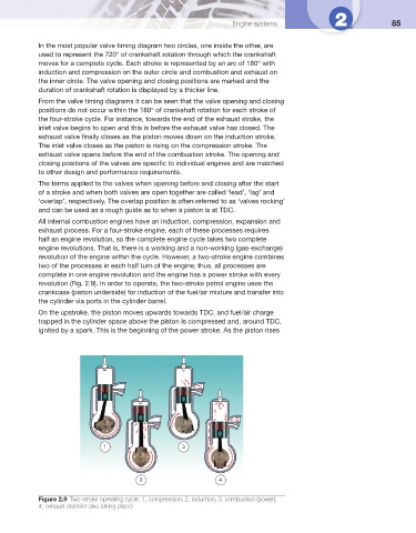
revolution ( Fig. 2.9 ). In order to operate, the two-stroke petrol engine uses the
crankcase (piston underside) for induction of the fuel/air mixture and transfer into
the cylinder via ports in the cylinder barrel.
On the upstroke, the piston moves upwards towards TDC, and fuel/air charge
trapped in the cylinder space above the piston is compressed and, around TDC,
ignited by a spark. This is the beginning of the power stroke. As the piston rises
1 3
2 4
Figure 2.9 Two-stroke operating cycle: 1, compression; 2, induction; 3, combustion (power);
4, exhaust (transfer also taking place)