
Page 100 - 05. Subyek Teknik Mesin - Automobile Mechanical and Electrical Systems Automotive Technology Vehicle Maintenance and Repair (Vehicle Maintenance Repr Nv2) by Tom Denton
P. 100
2
84 Automobile mechanical and electrical systems
On the induction stroke of a petrol engine (most types), air and petrol enter the
cylinder so the inlet valve in the inlet port must be open. In diesel, and gasoline
(petrol) direct injection (GDi) engines, only air enters the cylinder. A rotating
cam on the camshaft provides a lifting movement when it runs in contact with
a follower. A mechanical linkage is used to transfer the movement to the valve
stem and the valve is lifted off its seat so that the inlet port is opened to the
combustion chamber. The air and fuel charge or air charge can now enter the
cylinder. The inlet valve begins to open shortly before the piston reaches TDC.
The exhaust valve, which is operated by its own cam in the same way as the
Key fact inlet valve, is beginning to close as the piston passes TDC at the end of the
Valve overlap helps clear the exhaust stroke. Valve overlap helps clear the remaining exhaust gases from the
remaining exhaust gases from the combustion chamber. The incoming air charge fi lls the combustion chamber as
combustion chamber. the last quantity of exhaust gas leaves through the exhaust port. This is known
as ‘scavenging’; it helps cool the combustion chamber by removing hot exhaust
gases and gives a completely fresh air charge.
The terms TDC and BDC are used to describe the position of the piston and
crankshaft when the piston is at the end of a stroke and the axis of the piston
and crankshaft bearing journals are in a straight line and at 0° (TDC) and 180°
(BDC) of crankshaft revolution. To the abbreviations are added the letters ‘A’ to
indicate degrees ‘after’ TDC or BDC and the letter ‘B’ to indicate ‘before’ TDC or
BDC. See Figs 2.2 and 2.3 .
The camshaft (see Fig. 2.1 ) rotates once for the two revolutions of the crankshaft
Key fact during the four-stroke cycle. The drive from the crankshaft to the camshaft has
The camshaft rotates once for the a 2:1 ratio produced by the numbers of teeth on the driven and driver gears.
two revolutions of the crankshaft Rotational data for the camshaft is usually given as degrees of crankshaft
during the four-stroke cycle.
rotation and this should to be considered in relation to the four-stroke cycle. The
four-stroke cycle occurs over two full revolutions of the crankshaft, which is a
720° rotational movement.
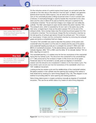
Looking at the four-stroke cycle and the relationships of the crankshaft rotation,
the piston position in the cylinder and the opening and closing of the valves is
best observed by looking at a valve timing diagram ( Fig. 2.8 ). This diagram is one
method of providing data for valve opening and closing positions.
Valve timing data is given in engine workshop manuals as degrees of crankshaft
revolution. This can be as written data or by means of valve timing diagrams.
Induction
ivo 0° evc Compression
3
Combustion
1
360° Exhaust
2
720°
1
2 540°
ivo - Inlet valve opens 180°
ivc - Inlet valve closes ivc evo
evo - Exhaust valve opens
evc - Exhaust valve closes Valve lead, lag & overlap (roll over numbers)
Figure 2.8 Valve timing diagrams: 1, lead; 2, lag; 3, overlap