
Page 103 - 05. Subyek Teknik Mesin - Automobile Mechanical and Electrical Systems Automotive Technology Vehicle Maintenance and Repair (Vehicle Maintenance Repr Nv2) by Tom Denton
P. 103
2
Engine systems 87
combustion chamber via cam-operated poppet valves. The incoming charge
forces the exhaust gases out via these valves (the cylinder scavenging process).
During the downwards movement of the piston, the hot expanding gases are
forcing the piston down the bore, producing torque at the crankshaft. This is the
expansion process. As the piston approaches BDC, the exhaust valve opens
and the remaining pressure in the exhaust gas starts the evacuation of the gases
in the cylinder via the open valves. As the piston moves further down to BDC,
inlet ports are exposed around the bottom part of the cylinder bore, which allow
the pressurized, fresh air charge from the air pump (or turbocharger) to fi ll the
cylinder, evacuating the remaining exhaust gas via the valves and completing the
exhaust and induction cycles.
At BDC, the cylinder contains a fresh air charge and the piston then begins
to move up the cylinder bore. The inlet ports are closed off by the piston
movement and the air charge is trapped and compressed by to the deceasing
volume in the cylinder. At a few degrees before TDC, the air temperature has
risen owing to the compression process and fuel is injected directly into the
combustion chamber, into the hot air charge, where it vaporizes, burns, and
generates thermal and pressure energy. This energy is converted to torque
at the crankshaft via the piston, connecting rod and crankshaft during the
downstroke.
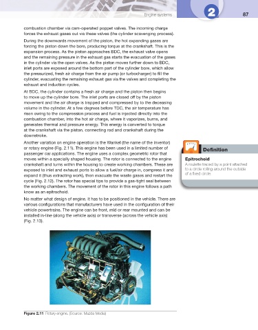
Another variation on engine operation is the Wankel (the name of the inventor)
or rotary engine ( Fig. 2.11 ). This engine has been used in a limited number of
Defi nition
passenger car applications. The engine uses a complex geometric rotor that
moves within a specially shaped housing. The rotor is connected to the engine Epitrochoid
crankshaft and turns within the housing to create working chambers. These are A roulette traced by a point attached
exposed to inlet and exhaust ports to allow a fuel/air charge in, compress it and to a circle rolling around the outside
of a fi xed circle.
expand it (thus extracting work), then evacuate the waste gases and restart the
cycle ( Fig. 2.12 ). The rotor has special tips to provide a gas-tight seal between
the working chambers. The movement of the rotor in this engine follows a path
know as an epitrochoid.
No matter what design of engine, it has to be positioned in the vehicle. There are
various confi gurations that manufacturers have used in the confi guration of their
vehicle powertrains. The engine can be front, mid or rear mounted and can be
installed in-line (along the vehicle axis) or transverse (across the vehicle axis)
( Fig. 2.13 ).
Figure 2.11 Rotary engine. (Source: Mazda Media)