
Page 104 - 05. Subyek Teknik Mesin - Automobile Mechanical and Electrical Systems Automotive Technology Vehicle Maintenance and Repair (Vehicle Maintenance Repr Nv2) by Tom Denton
P. 104
2
88 Automobile mechanical and electrical systems
Figure 2.12 Rotary engine cycle: starting with the top image, induction, compression, power,
exhaust. (Source: Wikimedia)
1 2 3 4
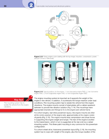
Figure 2.13 Typical positions for the engine: 1, front transverse engine FWD; 2, rear transverse
engine RWD; 3, front longitudinal engine FWD; 4, front longitudinal engine RWD
The engine mounting system is important as it supports the weight of the
Key fact engine in the vehicle. In addition, it counteracts the torque reaction under load
The mounting system has to conditions. The mounting system has to isolate the vehicle from the engine
isolate the vehicle from the engine vibrations. The engine mounts consist of steel plates with a rubber sandwich
vibrations.
between to provide the vibration isolation ( Fig. 2.14 ). The mountings have
appropriate brackets and fi ttings to fi x to the engine and vehicle frame.
For a front-engine, rear-drive powertrain layout, the engine mounts are often
at the centre position of the engine side, approximately at the engine centre
of gravity ( Fig. 2.15 ). The engine mounts bear compression and shear forces
in supporting the engine weight and torque. The rear of the engine is bolted
to the transmission, which in turn is supported at the rear end via a rubber
mounting system. This three-point mounting is very common for this powertrain
confi guration.
For a front-wheel drive, transverse powertrain layout ( Fig. 2.16 ), the mounting
system has to cope with weight of the engine, plus the torque reaction of the