
Page 102 - Automotive Engineering Powertrain Chassis System and Vehicle Body
P. 102
CH AP TER 4 .1 Digital engine control systems
BATTERY EP
PACK DW
POWER
ELECTRONICS AXLE
EP
ICE G EM T/A
HIGH-VOLTAGE
MP BUS MP AXLE
DW
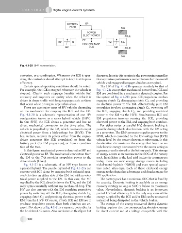
Fig. 4.1-20 SHV representation.
operation, or a combination. Whenever the ICE is oper- discussed later in this section is the powertrain controller
ating, the controller should attempt to keep it at its peak that optimizes performance and emissions for the overall
efficiency. vehicle and engages/disengages clutches as required.
Certain special operating conditions should be noted. The HV of Fig. 4.1-21b operates similarly to that of
For example, the ICE is stopped wherever the vehicle is Fig. 4.1-21a except that mechanical power from ICE and
stopped. Clearly, such stoppage benefits vehicle fuel EM are combined in a mechanism denoted coupler. For
economy and improves air quality when the vehicle is the system of Fig. 4.1-21b pure ICE propulsion involves
driven in dense traffic with long stoppages such as those engaging clutch C 1 disengaging clutch C 2 , and providing
that occur while driving in large urban areas. no electrical power to the EM. Alternatively, pure EM
There are two major types of HV vehicles depending propulsion involves disengaging clutch C 1 , switching off
on the mechanism for coupling the ICE and the EM. the ICE, engaging clutch C 2 , and providing electrical
Fig. 4.1-20 is a schematic representation of one HV power to the EM via the HVB. Simultaneous ICE and
configuration known as a series hybrid vehicle (SHV). EM propulsion involves running the ICE, providing
In this SHV, the ICE drives a generator and has no electrical power to the EM, and engaging both clutches.
direct mechanical connection to the drive axles. The For either series or parallel HV, dynamic braking is
vehicle is propelled by the EM, which receives its input possible during vehicle deceleration, with the EM acting
electrical power from a high-voltage bus (HVB). This as a generator. The EM/ generator supplies power to the
bus, in turn, receives its power either from the engine- HVB, which is converted to the low-voltage bus (LVB)
driven generator (for ICE propulsion) or from the voltage level by the power electronics subsystem. In this
battery pack (for EM propulsion), or from a combina- deceleration circumstance the energy that began as ve-
tion of the two. hicle kinetic energy is recovered with the motor acting as
In this figure, mechanical power is denoted as MP and a generator and is stored in the battery pack. This storage
electrical power as EP. The mechanical connection from of energy occurs as an increase in the SOC of the battery
the EM to the T/A provides propulsive power to the pack. In addition to the lead acid battery in common use
drive wheels (DWs). today, there are new energy storage means including
Fig. 4.1-21 is a schematic of an HV type known as nickel-metal-hydride (NiMH) and even special capaci-
a parallel hybrid. The parallel hybrid of Fig. 4.1-21a can tors called ultra-caps. Each of these electrical energy
operate with ICE alone by engaging both solenoid-oper- storage technologies has advantages and disadvantages for
ated clutches on either side of the EM but with no elec- HV application.
trical power supplied to the EM. In this case, the MP The battery pack has a maximum SOC that is fixed by
supplied by the ICE directly drives the T/A, and the EM its capacity. Dynamic braking is available as an energy
rotor spins essentially without any mechanical drag. This recovery strategy as long as SOC is below its maximum
HV can also operate with the EM supplying propulsive value. Nevertheless, dynamic braking is an important
power by switching off the ICE, disengaging clutch C 1 , part of HV fuel efficiency. It is the only way some of the
engaging clutch C 2 , and providing electrical power to the energy supplied by the ICE and/or EM can be recovered
EM from the HVB. Of course, if both ICE and EM are to instead of being dissipated in the vehicle brakes.
produce propulsive power, then both clutches are en- The storage of the energy recovered during dynamic
gaged. Not shown in Fig. 4.1-21 is a separate controller for braking requires that the corresponding electrical energy
the brushless DC motor. Also not shown in this figure but be direct current and at a voltage compatible with the
100