
Page 104 - Automotive Engineering Powertrain Chassis System and Vehicle Body
P. 104
CH AP TER 4 .1 Digital engine control systems
C Q 1 E D 1
N 1 N 2
(DC) V B V
1
C 2
CONTROL
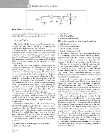
Fig. 4.1-23 DC to DC converter.
then the power flowing from the transformer secondary Vehicle speed
to a load will be at a peak voltage V 2 where ICE RPM and load
EM voltage and current
V 2 ¼ðN 2 =N 1 ÞV 1
The system outputs include control signals to:
The validity of this simple model for a transformer ICE throttle position
depends on many factors, but for an introduction to EM motor control inputs
transformer operating theory it is sufficient. Clutch engage/disengage
Conversion of DC electrical power from one voltage Switch ICE ignition on/off
to another can be accomplished using a transformer only In this vehicle, there is no direct mechanical link from
if the DC power is converted to AC power. Fig. 4.1-23 is the accelerator pedal to the throttle. Rather, the throttle
a greatly simplified schematic of a DC to DC converter in position (as measured by a sensor) is set by the control
which a transistor is used to convert an input DC signal to system via an electrical signal sent to an actuator (motor)
AC that is sent to a transformer for conversion to a dif- that moves the throttle in a system called drive-by-wire.
ferent voltage. The control system itself is a digital controller using
The control electronics supplies a pulsating signal to the inputs and outputs listed above and has the capability
the base B of transistor Q 1 , alternately switching it on of controlling the hybrid powertrain in many different
and off. When Q 1 is on (i.e., conducting), voltage V 1 is modes. These modes include starting from a standing
applied to the transformer primary (i.e., N 1 ). When Q 1 is stop, steady cruise, regenerative braking, recharging
off (i.e., nonconducting), transformer primary voltage is battery pack, and many others that are specific to a par-
zero. In this case, the pulsating AC voltage that is alter- ticular vehicle configuration.
nately V 1 and 0 applied to the primary results in an AC In almost all circumstances, it is desirable for the ICE
voltage in the secondary that is essentially N 2 /N 1 times to be off at all vehicle stops. Clearly, it is a waste of fuel
the primary voltage. This secondary voltage is converted and an unnecessary contribution to exhaust emissions for
to DC by rectification using diode D 1 and filtering via an ICE to run in a stopped vehicle. Exceptions to this rule
capacitor C. The secondary voltage is fed back to the involve cold-weather operations in which it is desirable or
control electronics, which varies the relative ON and even necessary to have some limited engine operations
OFF times to maintain V 2 at the desired level. with a stopped vehicle. In addition, a low-battery SOC
A variation of the circuit of Fig. 4.1-23 appears in might call for ICE operation at certain vehicle stops.
the power electronics module for conversion between When starting from a standing start, normally the EM
the LVB and the HVB. Of course, the specific details propulsion is used to accelerate the car to desired speed,
of the relevant power electronics depend on the HV assuming the battery has sufficient charge. If charge is
manufacturer. low, then the controller can engage the clutch to the ICE
Powertrain control for an HV is achieved using such that the EM can begin acceleration and at the same
a multimode digital control system. It is somewhat more time crank the ICE to start it. Then, depending on the
complicated than the digital engine control system time that the vehicle is in motion, the ICE can provide
discussed earlier in this chapter in that it must control an propulsive power and/or battery charge power. Should
ICE as well as an EM. In addition, it must achieve the the vehicle go to a steady cruise for engine operation near
balance between ICE and EM power, and it must engage its optimum, then the control strategy normally is to
or disengage the solenoid-operated clutches (if present). switch off the electric power to the EM and power the
The inputs to this controller come from sensors that vehicle solely with the ICE. In other cruise conditions,
measure:
the controller can balance power between ICE and EM in
Power demand from driver (accelerator pedal) a way that maximizes total fuel economy (subject to
SOC of battery pack emission constraints).
102