
Page 100 - Automotive Engineering Powertrain Chassis System and Vehicle Body
P. 100
CH AP TER 4 .1 Digital engine control systems
closed-loop operation in cars equipped with the three- directly into the intake port of the corresponding cylin-
way catalyst. As we have seen, the signal from the oxygen der during the intake stroke.
sensor is not useful for closed-loop control until the During the intake stroke, the intake valve is opened
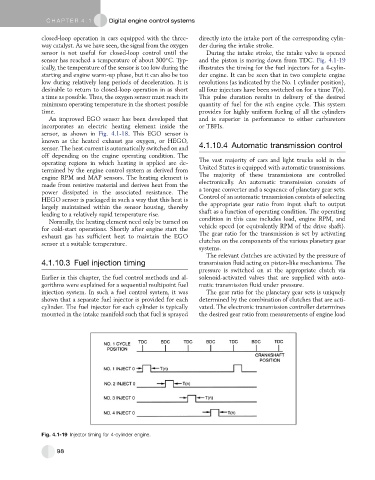
sensor has reached a temperature of about 300 C. Typ- and the piston is moving down from TDC. Fig. 4.1-19
ically, the temperature of the sensor is too low during the illustrates the timing for the fuel injectors for a 4-cylin-
starting and engine warm-up phase, but it can also be too der engine. It can be seen that in two complete engine
low during relatively long periods of deceleration. It is revolutions (as indicated by the No. 1 cylinder position),
desirable to return to closed-loop operation in as short all four injectors have been switched on for a time T(n).
a time as possible. Thus, the oxygen sensor must reach its This pulse duration results in delivery of the desired
minimum operating temperature in the shortest possible quantity of fuel for the nth engine cycle. This system
time. provides for highly uniform fueling of all the cylinders
An improved EGO sensor has been developed that and is superior in performance to either carburetors
incorporates an electric heating element inside the or TBFIs.
sensor, as shown in Fig. 4.1-18. This EGO sensor is
known as the heated exhaust gas oxygen, or HEGO,
sensor. The heat current is automatically switched on and 4.1.10.4 Automatic transmission control
off depending on the engine operating condition. The
operating regions in which heating is applied are de- The vast majority of cars and light trucks sold in the
termined by the engine control system as derived from United States is equipped with automatic transmissions.
engine RPM and MAP sensors. The heating element is The majority of these transmissions are controlled
made from resistive material and derives heat from the electronically. An automatic transmission consists of
power dissipated in the associated resistance. The a torque converter and a sequence of planetary gear sets.
HEGO sensor is packaged in such a way that this heat is Control of an automatic transmission consists of selecting
largely maintained within the sensor housing, thereby the appropriate gear ratio from input shaft to output
leading to a relatively rapid temperature rise. shaft as a function of operating condition. The operating
Normally, the heating element need only be turned on condition in this case includes load, engine RPM, and
for cold-start operations. Shortly after engine start the vehicle speed (or equivalently RPM of the drive shaft).
exhaust gas has sufficient heat to maintain the EGO The gear ratio for the transmission is set by activating
sensor at a suitable temperature. clutches on the components of the various planetary gear
systems.
The relevant clutches are activated by the pressure of
4.1.10.3 Fuel injection timing transmission fluid acting on piston-like mechanisms. The
pressure is switched on at the appropriate clutch via
Earlier in this chapter, the fuel control methods and al- solenoid-activated valves that are supplied with auto-
gorithms were explained for a sequential multipoint fuel matic transmission fluid under pressure.
injection system. In such a fuel control system, it was The gear ratio for the planetary gear sets is uniquely
shown that a separate fuel injector is provided for each determined by the combination of clutches that are acti-
cylinder. The fuel injector for each cylinder is typically vated. The electronic transmission controller determines
mounted in the intake manifold such that fuel is sprayed the desired gear ratio from measurements of engine load
Fig. 4.1-19 Injector timing for 4-cylinder engine.
98